
- Forum
- General chat
- General discussion
- Any radmon experts here? My unit has failed after water ingress
Any radmon experts here? My unit has failed after water ingress
2 years 9 months ago - 2 years 9 months ago #6604
by Simomax
Replied by Simomax on topic Any radmon experts here? My unit has failed after water ingress
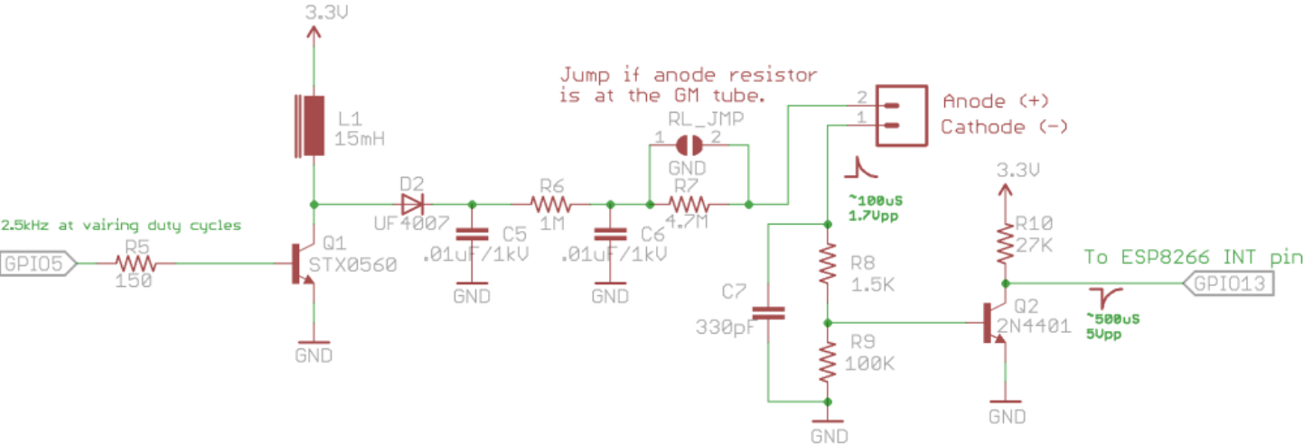
There is really very little to go wrong with the HV PSU generally and I would be surprised if any passives have been damaged. Looking at your scope display it is showing around 2.4 VPP (volts peak to peak), this should be around 3.3 VPP. This could be telling or it could be your scope is a bit out of calibration. Ignore the -1.52V on my scope display, I hadn't set it up for reading the voltage. Count the squares instead. Mine shows a nice 3.3 VPP. Ignore the PWM frequency for now. The scope trace looks about right. Similar pattern to mine. It is worth noting that one of the components may have had a good 400v thrown at it via the water ingress. The current is very low, but there is still a potential for one of the components to be damaged, such as Q1 or the ESP. The ESP will be the most sensitive part of the whole thing.
It could be something on the board pulling this down. Faulty transistor? Inductor still got water in it, causing it to fail? Diode or resistor open circuit? Hard to say without having it in front of me. I would start from scratch and then follow a path of testing each part one by one.
1, Check voltages. First thing to do, always make sure you have a good supply. Check to measure 3.3v between GND and VCC on the ESP itself, nowhere else on the board, right on the ESP. These ESPs can run down to about 2.4 volts if memory serves me right, so if the PSU is faulty, or something pulling it down then it might look OK as the ESP is running itself, but doesn't have the voltage to fire the HV.
2, Assuming the supply voltage is good, then remove the ESP from the board completely. Write a quick sketch and upload to test GPIO5. I would test for high/low and PWM states. Use your scope to check the PWM output.
3, Assuming all of that is good then I would start looking at the board. R5 is a fairly low resistance, so a short between base and emitter would pull down the PWM voltage to ground, but as there is 47 ohms resistance there it wouldn't pull it down completely. A short between base and collector would also give a strange reading and keep the PWM somewhat high. Check Q1. Might be worth removing L1 and D2 to get a clean reading of Q1 as this effectively removes it from circuit. Also check D2 out of circuit. I would be surprised if the other passives (C5, C6, R6 and R7) were faulty, but it's not like resistors and capacitors haven't gone bad before.
Those are the things I would do to try and track down the fault. Check supply voltage - if bad could be the 3.3v regulator, ESP or another component pulling the thing down. It will require parts removing to ascertain the faulty part itself. Then check the ESP itself, out of the board. It is no good doing any tests whatsoever with the ESP still connected to the counter as the other components may give erroneous results. And finally, start looking at the other components on the HV PSU. The switching transistor, the diode etc.
Last edit: 2 years 9 months ago by Simomax.
Please Log in or Create an account to join the conversation.
2 years 9 months ago #6606
by Juzzie
Owner and operator of "southofhobart" monitoring stations.
Replied by Juzzie on topic Any radmon experts here? My unit has failed after water ingress
Great advice there simomax.
The power supply was the first thing to go on my unit, and I now use an external 3.3v regulator board patched in to the derelect PCB. You could not tell by looking but corrosion had disolved the copper circuitry on the PCB, and when tempted with a tiny amount of pressure, the original surface mount regulator just fell off - with bits of the curcuit attached.
I don't have/use a scope - just a trusty multimeter, a lead with a gigaohm resistor, and a copy of the schematic. "Follow the circuit and test every step of the way".
Hope this makes sense - I am lacking the knowledge of correct terminology.
Owner and operator of "southofhobart" monitoring stations.
Please Log in or Create an account to join the conversation.

2 years 9 months ago #6608
by nzoomed
Replied by nzoomed on topic Any radmon experts here? My unit has failed after water ingress
The ESP is definitely getting the 3.3v on my multimeter. I was pretty sure the scope was showing an accurate voltage per grid division, but will doube check the board, im pretty confident the ESP ic counting, that PWM signal you saw on my scope only shows while the unit is counting, so it must be doing its thing, and I can get it to register and transmit counts when touching the negative pin of the GM terminals.
Im suspecting Q1 or Q2 is the problem, Q1 is the switching transistor if im not mistaken?
Im suspecting Q1 or Q2 is the problem, Q1 is the switching transistor if im not mistaken?
Please Log in or Create an account to join the conversation.
2 years 9 months ago - 2 years 9 months ago #6609
by Juzzie
Q1
Owner and operator of "southofhobart" monitoring stations.
Replied by Juzzie on topic Any radmon experts here? My unit has failed after water ingress
Q1
Owner and operator of "southofhobart" monitoring stations.
Attachments:
Last edit: 2 years 9 months ago by Juzzie.
Please Log in or Create an account to join the conversation.
2 years 9 months ago - 2 years 9 months ago #6611
by nzoomed
Replied by nzoomed on topic Any radmon experts here? My unit has failed after water ingress
I've tested all the traces on that board for the HT supply and everything is all OK including the passives.
I'm leaning towards the transistor being at fault.
Doesn't seem to be a common component.
I can't see it listed anywhere at RS.
I am getting an output on the scope when probing the transistor, but it looked really odd. Will see if I can get a photo.
I'm leaning towards the transistor being at fault.
Doesn't seem to be a common component.
I can't see it listed anywhere at RS.
I am getting an output on the scope when probing the transistor, but it looked really odd. Will see if I can get a photo.
Last edit: 2 years 9 months ago by nzoomed.
Please Log in or Create an account to join the conversation.
2 years 9 months ago #6612
by Simomax
Replied by Simomax on topic Any radmon experts here? My unit has failed after water ingress
It looks like the STX0560 has become obsolete. I can't find one for love nor money. There is a thread on EEVblog about it:
https://www.eevblog.com/forum/projects/stx0560-equivalent/
You could try STX13005-APH as an alternative. I have one of these running in a very similar counter. It is on my breadboard counter, and is based on the GK v5.5 schematic, which I believe is older than the GK-Radmon. It appears the pinout is the same, but worth your own sanity check against the datasheets.
Or, you could contact BroHogan (DIYGeiger) and see if he has any spares he could sell.
Please Log in or Create an account to join the conversation.
Moderators: Gamma-Man
- Forum
- General chat
- General discussion
- Any radmon experts here? My unit has failed after water ingress
Time to create page: 0.211 seconds