
- Forum
- General chat
- General discussion
- Any radmon experts here? My unit has failed after water ingress
Any radmon experts here? My unit has failed after water ingress

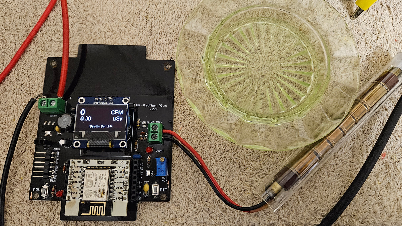
When i touch the negative pin of the GM tube terminals, it causes the unit to register a reading.
Ive gone over the solder joints and given the whole board an ultrasonic clean to get rid of corrosion, etc. And lastly, is there any better quality enclosure with a window? The one I bought with the clear window went all crazed and yellow on the lid and started to break down from the sun's UV.Have added photo of board running. Screen has suffered a bit of damage but still readable.
Please Log in or Create an account to join the conversation.
The voltage that is stated on the oled is simply calculated from the PWM in software, there is nothing that actually reads the voltage. It looks like the detection circuit is working by you getting readings when you touch the negative of the tube, and the SPI is working for the oled. You should be getting something on your oscilloscope for the PWM output to the HV PSU. I suspect the ESP8266 may have some internal damage under the metal can that is causing the PWM to fail. I suspect the ESP is at fault and may require replacement.
Please Log in or Create an account to join the conversation.
Not sure if the transistors on the board that drive it are damaged or not, but either way cant get anything to show on my scope.
Please Log in or Create an account to join the conversation.
Owner and operator of "southofhobart" monitoring stations.
Please Log in or Create an account to join the conversation.

nzoomed, I have the GK Radmon Basic. It seems the differences, board aside, are in the Arduino code and the plus is browser configurable. I was going to suggest uploading my version of code to try and diagnose as it keeps the HV on all the time, but not sure if it would work on the plus or not. It's been a while since playing with the GK Radmon but I remember that the stock code will go into a deep sleep for 5 minutes, wake up, powers the HV and starts to count for 15 or 30 seconds, then submits to radmon.org, then goes to sleep again for 5 minutes and turns the HV off. Just a sanity check; you have been checking the PWM whilst the counter is awake?
This is from the GK website:
I wrote new code for my GK Radmon as I wanted it to act more like the NetIO GC10 where it is constantly sampling over a minute and calculating CPM based on 60 seconds of counts. My HV stays on all the time and the counter never goes to sleep as the power supply was always available - I don't run it on batteries/solar. Maybe you can use your browser to stop it going into sleep mode?A count and sleep cycle keeps power usage to a minimum. During the count cycle HV is supplied to the tube and events are counted. At the end of the cycle the kit connects to WiFi and sends its readings.
Following the transmission, the RadMon will enter sleep mode. The power demand drops sharply. At the end of the sleep cycle the RadMon wakes up and repeats the cycles.
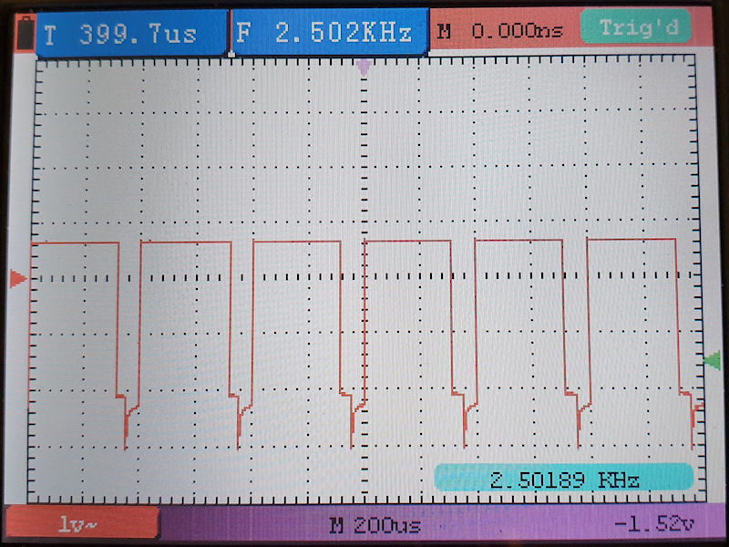
I also checked the PWM on mine with a scope and the trace is below. I connected my scope to the female pin header next to the ESP pin headers, so is coming right from the ESP and nowhere else on the board. If I was testing the ESP I would remove it from the counter and power up on an external 3.3v supply and write a very basic code to simply test the output on GPIO5. Maybe test for high and low outputs, then test for PWM. If it has failed on GPIO5 it may be possible to use another GPIO instead of GPIO5, but that would require some modification to the circuit.
Edit: Maybe not possible to use another pin for PWM. It looks like all of the pins are used on the ESP after looking at the schematic.
Attachments:
Please Log in or Create an account to join the conversation.
nzoomed, I have the GK Radmon Basic. It seems the differences, board aside, are in the Arduino code and the plus is browser configurable. I was going to suggest uploading my version of code to try and diagnose as it keeps the HV on all the time, but not sure if it would work on the plus or not. It's been a while since playing with the GK Radmon but I remember that the stock code will go into a deep sleep for 5 minutes, wake up, powers the HV and starts to count for 15 or 30 seconds, then submits to radmon.org, then goes to sleep again for 5 minutes and turns the HV off. Just a sanity check; you have been checking the PWM whilst the counter is awake?
This is from the GK website:
I wrote new code for my GK Radmon as I wanted it to act more like the NetIO GC10 where it is constantly sampling over a minute and calculating CPM based on 60 seconds of counts. My HV stays on all the time and the counter never goes to sleep as the power supply was always available - I don't run it on batteries/solar. Maybe you can use your browser to stop it going into sleep mode?A count and sleep cycle keeps power usage to a minimum. During the count cycle HV is supplied to the tube and events are counted. At the end of the cycle the kit connects to WiFi and sends its readings.
Following the transmission, the RadMon will enter sleep mode. The power demand drops sharply. At the end of the sleep cycle the RadMon wakes up and repeats the cycles.
I also checked the PWM on mine with a scope and the trace is below. I connected my scope to the female pin header next to the ESP pin headers, so is coming right from the ESP and nowhere else on the board. If I was testing the ESP I would remove it from the counter and power up on an external 3.3v supply and write a very basic code to simply test the output on GPIO5. Maybe test for high and low outputs, then test for PWM. If it has failed on GPIO5 it may be possible to use another GPIO instead of GPIO5, but that would require some modification to the circuit.
Edit: Maybe not possible to use another pin for PWM. It looks like all of the pins are used on the ESP after looking at the schematic.
My board has similar damage to yours juzzie but the traces appear OK, just the solder mask lifting in places.
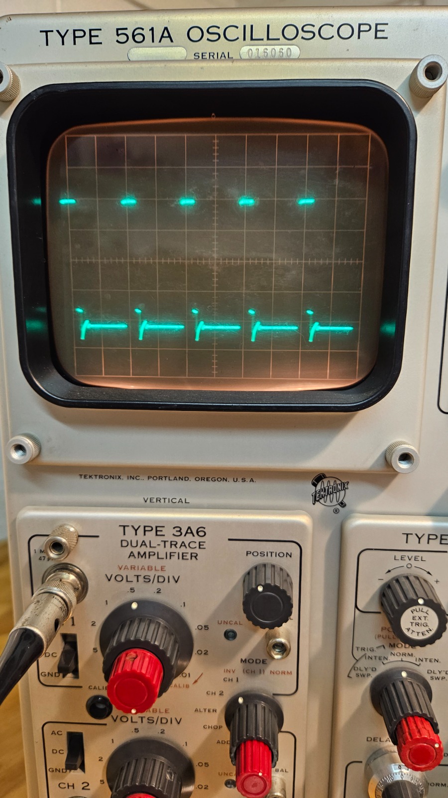
here is a photo of my scope output on GPIO5 while counting, looks like this is OK?
What should i be testing on the board if im getting no HT?
I see some sort of signal on one of the pins of Q1, just needing to work my way between GPIO5 and the HT.
Please Log in or Create an account to join the conversation.
- Forum
- General chat
- General discussion
- Any radmon experts here? My unit has failed after water ingress