
SBT-11A Photographs
- ChrisLX200
-

- Offline
- Elite Member
-

Less
More
- Posts: 161
- Thank you received: 8
8 years 11 months ago #3416
by ChrisLX200
Replied by ChrisLX200 on topic SBT-11A Photographs
My one outstanding (and overdue) order is from Sovtube for one SBT-11A tube. I hope HM Customs & Excise people have not had their grubby hands inside it as the tube probably won't survive the experience...
Please Log in or Create an account to join the conversation.
- ChrisLX200
-
- Offline
- Elite Member
-
Less
More
- Posts: 161
- Thank you received: 8
8 years 11 months ago #3417
by ChrisLX200
Replied by ChrisLX200 on topic SBT-11A Photographs
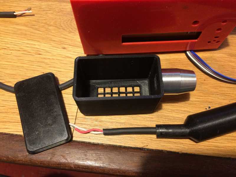
On the expectation that the other tube will eventually turn up in the post I printed a second tube holder or 'wand'. This is a design leached off Thingiverse, but modified with an alloy furrule where the handle fits into the rectangular box holding the SBT-11A tube. The ferrule is epoxied onto the box and offers a stronger joint. The 5mm connecting cable runs through the handle.
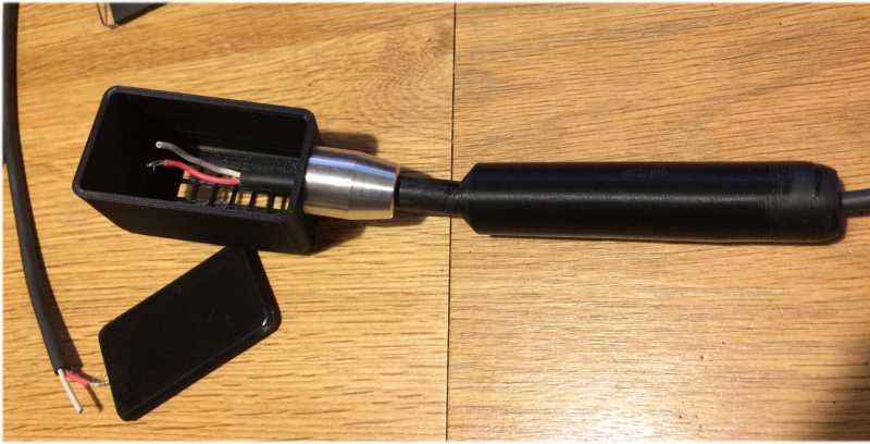
The final image shows the 1 meter cable is terminated with a push-to-connect 4-pin plug, it's polarised (of course) and is very quick to connect and disconnect. The only ones I had in stock are 4-pin plugs and sockets so only two of the pins are acutally in use.
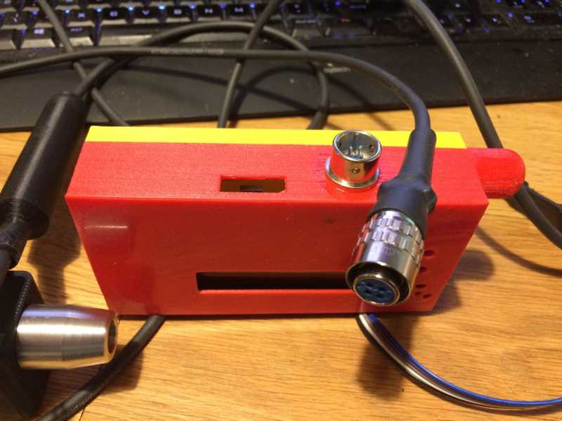
The final image shows the 1 meter cable is terminated with a push-to-connect 4-pin plug, it's polarised (of course) and is very quick to connect and disconnect. The only ones I had in stock are 4-pin plugs and sockets so only two of the pins are acutally in use.
Please Log in or Create an account to join the conversation.
- ChrisLX200
-
- Offline
- Elite Member
-
Less
More
- Posts: 161
- Thank you received: 8
8 years 11 months ago #3437
by ChrisLX200
Replied by ChrisLX200 on topic SBT-11A Photographs
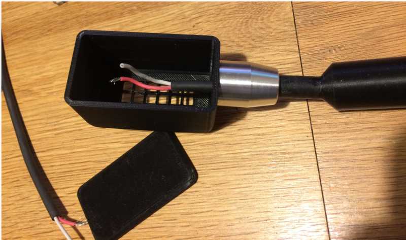
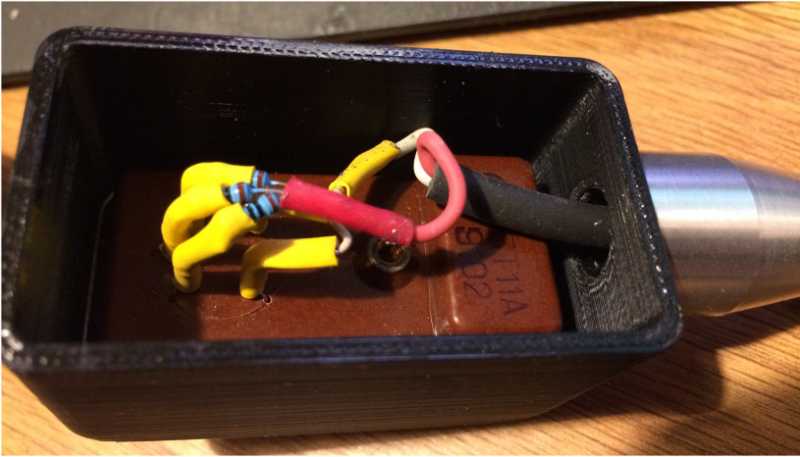
With regards to connecting a lead to the SBT-11A - although some owners like to solder directly to the pins I was less than enthusiastic about attempting this. I had used a dedicated socket on my first SBT-11A and it worked well (meaning soldering was not a requirement to get a good connection) so I looked around in my junk box for something similar that I could use. I had no luck finding a compatible 5-pin socket but I thought maybe I could just extract the female pins from a 4-way computer fan plug because the pins looked to be about the right size. If you press the tiny retaining tabs the pins pull out of the plastic block and I tried pushing them onto the SBT-11A pins - a perfect firm fit ") OK, not as good as a dedicated socket perhaps but it saves risking damage to the tube by soldering. I clipped the socket pins as short as possible and soldered a 10M Ohm resistor to the three which plugged onto the postive terminals, those for two negative pins were simply soldered together for a common ground connection. I used heat-shrink tube to cover each of the five pins including the resistors so it's all neat and tidy.
OK, not as good as a dedicated socket perhaps but it saves risking damage to the tube by soldering. I clipped the socket pins as short as possible and soldered a 10M Ohm resistor to the three which plugged onto the postive terminals, those for two negative pins were simply soldered together for a common ground connection. I used heat-shrink tube to cover each of the five pins including the resistors so it's all neat and tidy.
OK, not as good as a dedicated socket perhaps but it saves risking damage to the tube by soldering. I clipped the socket pins as short as possible and soldered a 10M Ohm resistor to the three which plugged onto the postive terminals, those for two negative pins were simply soldered together for a common ground connection. I used heat-shrink tube to cover each of the five pins including the resistors so it's all neat and tidy.
Please Log in or Create an account to join the conversation.
8 years 11 months ago #3438
by Juzzie
Owner and operator of "southofhobart" monitoring stations.
Replied by Juzzie on topic SBT-11A Photographs
very tidy, nice one!
Owner and operator of "southofhobart" monitoring stations.
Please Log in or Create an account to join the conversation.
- Sonarflash
-
 Topic Author
- Offline
- Premium Member
-

- Blind since 1966 - 51+ years with insight.
Less
More
- Posts: 137
- Thank you received: 15
8 years 11 months ago #3439
by Sonarflash
Replied by Sonarflash on topic SBT-11A Photographs
Thanks for the idea of using those small clip connectors. I have several with wires. Tried 5 on an SBT-11A. Much better than the clips I broke out of an old 9 pin vacuum tube socket.
I would appreciate some feedback about this matter of using 3 10 megohm resistors on the 3 anode pins. As mentioned, I've tried that and also made all three pins common, then coupling to 1 10 megohm resistor. Today, I used 3 4.7 megohm resistors, twisted them together, then added another 4.7 megohm resistor in series to the GC. That also worked, with each anode bar having approx. 10 megohm at any one time.
Last year, when I asked him, Atomic Dave suggested the 3 resistors because of voltage drops on each anode bar caused by intense bombardment. I can't quite wrap my head around this. Not to mention trying to figure out the electronics/physics of 3 anodes and 3 resistors in effect in parallel, but not...
With one resistor and all three anode pins common, I don't notice any variation. Course, that might be different if one was watching pulses on a dual-trace oscilloscope.
Has anybody tried saturating an SBT-11A with an americium smoke detector button taking readings first with the 3 resistors, then with just one resistor? If the count rate drops a few thousand CPM, that would be a good indicator.
Once I'm settled in at the new home, I'll try to run that experiment.
Regards
Please Log in or Create an account to join the conversation.
- ChrisLX200
-
- Offline
- Elite Member
-
Less
More
- Posts: 161
- Thank you received: 8
8 years 11 months ago - 8 years 11 months ago #3441
by ChrisLX200
Replied by ChrisLX200 on topic SBT-11A Photographs
I've been caught out again by this damn forum - it 'times out' while typing a reply and loses your text when you hit the 'Submit' button. Very annoying!! I'll have to use an external editor from now on.
See if I can start again. Anyway, I just copied the arrangement of the socketed SBT-11A which I received through the post, that had the three 10M Ohm resistors for the anode pins. I had not thought about it much before but if connected this way the three anode pins will be isolated from each other via their respective resistor. If commoned then passed through a single termination resistor the anodes will not be isolated from each other. The three discrete segments of the SBT-11A can operate individually, each able to generate a pulse as that part of the tube array is triggered.
Consider the case where two segments are triggered sequentially but separated by a short time interval. When a pulse is generated then there is a recovery period during which that segment will be depolarised and refractory, it will be unable to generate another pulse until the potential difference for that segment is re-established. If the pulse from the second segment occurred during this period (i.e., very close together - or even overlapping slightly), and if the segments were not isolated from each other then this may prevent that second pulse ever reaching the detector. Using a resistor on each pin provide a high impedance connection between the two anodes so the pulse from the second should be unaffected.
As you suggest, the effects of this would likely be seen during high count rates where the maximum count would (possibly) be reduced, and this would be progressive as count rate increased.
This is just off the top of my head and possibly complete BS but it could be tested in the manner you suggest.
See if I can start again. Anyway, I just copied the arrangement of the socketed SBT-11A which I received through the post, that had the three 10M Ohm resistors for the anode pins. I had not thought about it much before but if connected this way the three anode pins will be isolated from each other via their respective resistor. If commoned then passed through a single termination resistor the anodes will not be isolated from each other. The three discrete segments of the SBT-11A can operate individually, each able to generate a pulse as that part of the tube array is triggered.
Consider the case where two segments are triggered sequentially but separated by a short time interval. When a pulse is generated then there is a recovery period during which that segment will be depolarised and refractory, it will be unable to generate another pulse until the potential difference for that segment is re-established. If the pulse from the second segment occurred during this period (i.e., very close together - or even overlapping slightly), and if the segments were not isolated from each other then this may prevent that second pulse ever reaching the detector. Using a resistor on each pin provide a high impedance connection between the two anodes so the pulse from the second should be unaffected.
As you suggest, the effects of this would likely be seen during high count rates where the maximum count would (possibly) be reduced, and this would be progressive as count rate increased.
This is just off the top of my head and possibly complete BS
but it could be tested in the manner you suggest.
Last edit: 8 years 11 months ago by ChrisLX200.
Please Log in or Create an account to join the conversation.
Moderators: Gamma-Man
Time to create page: 0.190 seconds