
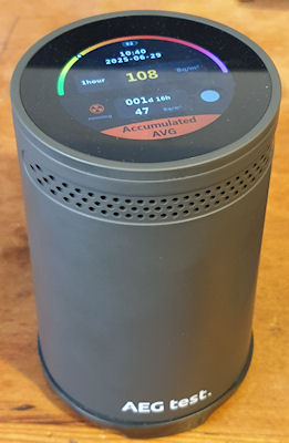
AEGTest Hound-3699 Radon Monitor
1 year 1 month ago - 1 year 1 month ago #7427
by Simomax
AEGTest Hound-3699 Radon Monitor was created by Simomax
AEGTest Hound-3699 Radon Monitor Teardown
( Many high resolution images of the teardown are here .)
I have been getting to know Radon quite a bit more of late. I manage a couple of sites at work and these are in Radon areas. I have used the Airthings Corentium and also fitted an Airthings View Radon 2989 in the basement of one of the sites. Monitoring is ongoing. I have also been experimenting with Radon a little too – discovering it’s progeny. I have also discovered that many (all?) of my U-238 sources also emit small amounts of Radon, local to their storage and I want to keep an eye on that, so I bought myself a Radon monitor – a AEGTest Hound-3699.
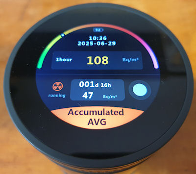
All in all it’s not a bad unit. £120 shipped from the jungle site. I like the screen and the touch on it is very nice. You can use quick light touches, just like a mobile phone, and it is fast to react. The up/down selections are a bit clunky though. It is fairly easy to use and a neat feature is it will automatically generate PDF reports – Set it up, let it run, plug into PC, Looks like a USB stick, grab PDF, put back in service. It is quite a neat feature. A sample report PDF is attached below.I was going to do a bit of a review on it, maybe a look inside, but when I came to make a copy of the manual (there is no electronic version available) I noticed it said “Any unauthorized copying or reproduction of this manual is strictly prohibited without prior written permission from AEG test.” Like, WTF? It’s a manual. They should be free for all. It is no good without the product, but may help someone actually purchase the correct product if the manual is available without purchasing the product itself.
I really dislike that kind of thing. So I scoured the manual (and the box, and the device) (which sadly I can’t copy and upload here) and looked for everything else it said I can’t do — and guess what? Nothing.
It doesn’t say I can’t tear it down.
It doesn’t say I can’t identify the parts.
It doesn’t say I can’t reverse engineer sections to see how it ticks.
It doesn’t say I can’t probe the circuits to trace where the data flows.
So I'm going to do all of that. Every bit of it. ALL OF IT.

The following is a detailed teardown, IC identification and a brief reverse engineering. The following post will be about gaining access to the locked ‘Admin’ menu (that they don’t want you in too, but they didn’t say I can't break in!). Then hopefully soon a modification to enable this little puppy to talk to the internet. If the manufacturer won’t let me do X, I will most certainly do Y and Z. They can bite my shiny metal ass.
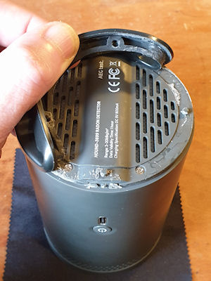
First off is getting into the bugger. They don’t really want you inside this thing. The case is clipped together at the sides, with two screws at the bottom under a rubber-baby-buggy-bumper that is glued in place. I’m guessing a line between not letting anyone inside and keeping the unit serviceable. A bit too much brute force could rip of destroy the rubber-baby-buggy-bumper. I had to tease it off very gently using a flat screwdriver, lots of force and a bit of time. Eventually I had gotten enough of it back without breaking anything and revealed the two screws. Take out the two screws then crack it open by squeezing it, and use a spudger to pop open the clips – two each side. After disassembling and reassembling a few times, it becomes quite easy to just squeeze in the right place to pop it open. Once a couple of clips are free it is much easier.
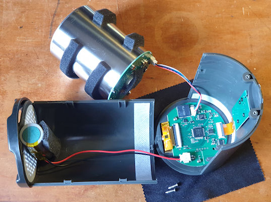
After opening it comes apart into three pieces – two halves of the case and the ionization chamber. The chamber is connected to the mainboard with a small JST connector. It has a squeezy lever to unlock the connector and it will disconnect fairly easily. The battery is also connected to the mainboard and it would be prudent to disconnect the battery and put to one side if playing about with the insides of the unit, unless you needed it powered on. Those INR21700 batteries can give out a huge amount of current – so don’t short it or you will have a really bad day.
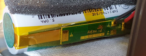
The battery is (by the looks of it) a genuine Samsung INR21700/50E, the specifications are:
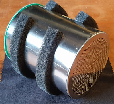
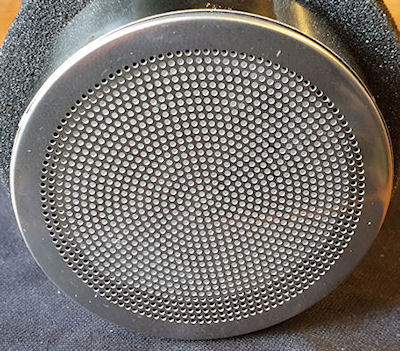
Now the chamber. Not particularly unusual to me. It isn’t dissimilar to ion-chamber radiation meters such as the CDV-715. This works on a pulsed output, much like GM tubes, so should be fairly easy to mod. The chamber is open to the air but I am unsure of the exact mode of operation. I have a feeling that some kind of charge accumulates, and then when it gets so much, it ionizes and creates a pulse. I have had some quite strange effects with it either not counting or counting too much, but generally when I ground myself and the chamber whilst reassembling this reduces funniness a lot.

The chamber measurements:
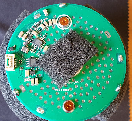

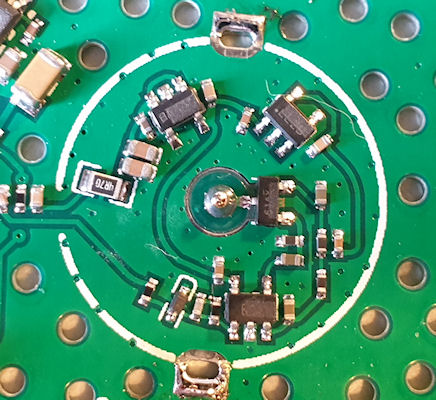
This is the PCB on the rear of the chamber. The top part is the HV stage and the lower part is the detection/pulse stage. There is an unknown IC that neither I nor Lala (AI) can find. I think it may be a stable voltage reference for the pulse – I could be wrong. The other two SOP-8s have had their markings removed. The one at the top in the HV stage is probably a switching IC as it has an inductor to its lower left and some hefty caps. The other SOP-8 is either an amp or comparator, or something similar. The tiny IC is quite unknown.Looking at the connector it’s pins (going from top to bottom) are as follows:
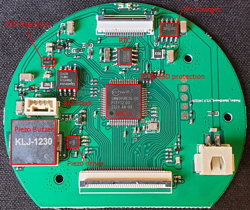
The mainboard has a few bits and pieces on it (datasheets linked below). Right at the top is the indicator LEDs (reversed). The MCU is a SWM34SRET6 (ARM Cortex M33). We also have an RTC above the MCU, some ESD protection on theSPI/I2C USB lines. Over at the top left an LDO regulator and just under that to the right is an 8M flash IC – It probably stores the PDF on that. The big thing at the bottom left is a Piezo buzzer for the bleeps and alarms, and to the right of that is a driver IC for the buzzer.
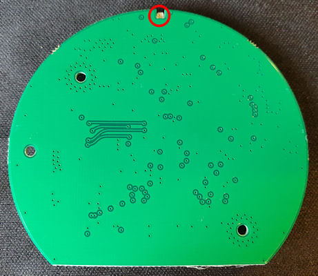
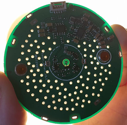
The rear of the mainboard is boring.
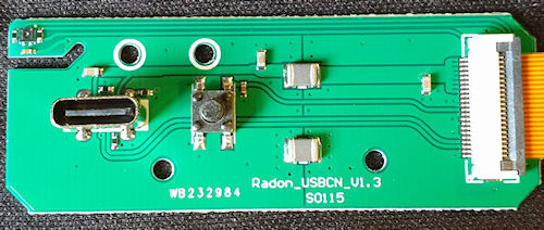
The USB port and power switch PCB. This just has the USB C connector, power button but also a sneaky hidden sensor. The sensor is a temperature and humidity sensor – but the manufacturers don’t have that displayed at all, and I think I know why. At first I had trouble identifying it so Lala (AI) helped. It looks just like a SHT30-DIS (or similar) so I think this may be a copy of the SHT30-DIS (or similar) and because of that they are not including the readings. It shows in the report PDF two fields – Temperature alarm and Humidity alarm, and both show ‘not support’.
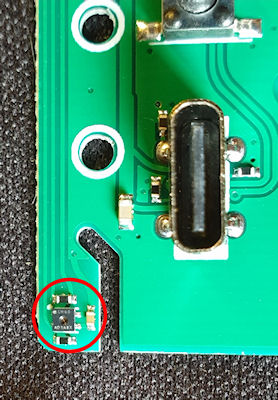
You can see the sensor a little more clearly in the above image. There is a cut-away in the PCB to help insulate the sensor from the rest of the board. The sensor is also mounted very close to the battery, so it may be used for monitoring battery temp, and as this will change during charging so that might be another reason they are not showing the values.

The last bit is the JTAG header pins on the board. And they are, just that.
And that just about wraps this up. Next post will be accessing the ‘Admin’ menu, and if I can manage to get my mod working properly, I’ll certainly post about that.
Datasheets for the ICs:
https://www.onsemi.cn/download/data-sheet/pdf/ncp585-d.pdf
https://www.digikey.com/en/products/detail/evvo/TP4057/22482076
https://mm.digikey.com/Volume0/opasdata/d220001/medias/docus/5010/TP4057.pdf
https://www.makerguides.com/wp-content/uploads/2025/01/BM8563-datasheet.pdf
https://datasheet.lcsc.com/lcsc/2108131930_TECH-PUBLIC-TPUSBLC6-2SC6_C558442.pdf
( Many high resolution images of the teardown are here .)
I have been getting to know Radon quite a bit more of late. I manage a couple of sites at work and these are in Radon areas. I have used the Airthings Corentium and also fitted an Airthings View Radon 2989 in the basement of one of the sites. Monitoring is ongoing. I have also been experimenting with Radon a little too – discovering it’s progeny. I have also discovered that many (all?) of my U-238 sources also emit small amounts of Radon, local to their storage and I want to keep an eye on that, so I bought myself a Radon monitor – a AEGTest Hound-3699.
All in all it’s not a bad unit. £120 shipped from the jungle site. I like the screen and the touch on it is very nice. You can use quick light touches, just like a mobile phone, and it is fast to react. The up/down selections are a bit clunky though. It is fairly easy to use and a neat feature is it will automatically generate PDF reports – Set it up, let it run, plug into PC, Looks like a USB stick, grab PDF, put back in service. It is quite a neat feature. A sample report PDF is attached below.I was going to do a bit of a review on it, maybe a look inside, but when I came to make a copy of the manual (there is no electronic version available) I noticed it said “Any unauthorized copying or reproduction of this manual is strictly prohibited without prior written permission from AEG test.” Like, WTF? It’s a manual. They should be free for all. It is no good without the product, but may help someone actually purchase the correct product if the manual is available without purchasing the product itself.
I really dislike that kind of thing. So I scoured the manual (and the box, and the device) (which sadly I can’t copy and upload here) and looked for everything else it said I can’t do — and guess what? Nothing.
It doesn’t say I can’t tear it down.
It doesn’t say I can’t identify the parts.
It doesn’t say I can’t reverse engineer sections to see how it ticks.
It doesn’t say I can’t probe the circuits to trace where the data flows.
So I'm going to do all of that. Every bit of it. ALL OF IT.
The following is a detailed teardown, IC identification and a brief reverse engineering. The following post will be about gaining access to the locked ‘Admin’ menu (that they don’t want you in too, but they didn’t say I can't break in!). Then hopefully soon a modification to enable this little puppy to talk to the internet. If the manufacturer won’t let me do X, I will most certainly do Y and Z. They can bite my shiny metal ass.
First off is getting into the bugger. They don’t really want you inside this thing. The case is clipped together at the sides, with two screws at the bottom under a rubber-baby-buggy-bumper that is glued in place. I’m guessing a line between not letting anyone inside and keeping the unit serviceable. A bit too much brute force could rip of destroy the rubber-baby-buggy-bumper. I had to tease it off very gently using a flat screwdriver, lots of force and a bit of time. Eventually I had gotten enough of it back without breaking anything and revealed the two screws. Take out the two screws then crack it open by squeezing it, and use a spudger to pop open the clips – two each side. After disassembling and reassembling a few times, it becomes quite easy to just squeeze in the right place to pop it open. Once a couple of clips are free it is much easier.
After opening it comes apart into three pieces – two halves of the case and the ionization chamber. The chamber is connected to the mainboard with a small JST connector. It has a squeezy lever to unlock the connector and it will disconnect fairly easily. The battery is also connected to the mainboard and it would be prudent to disconnect the battery and put to one side if playing about with the insides of the unit, unless you needed it powered on. Those INR21700 batteries can give out a huge amount of current – so don’t short it or you will have a really bad day.
The battery is (by the looks of it) a genuine Samsung INR21700/50E, the specifications are:
- Model: INR21700-50E
- Size: 21700 (21mm x 700mm)
- Head type (Positive terminal): Flat Top
- Maximum Capacity: 5000mAh
- Typical Capacity: 4900mAh (0.2C discharge)
- Peak discharge rating: 15A
- Continuous discharge Rating: 9.8A
- Nominal voltage: 3.6V
- End-of-charge voltage: 4.20V
- End-of-discharge Voltage: 2.50V
- Rechargeable: Yes
- Protection circuit: Unprotected
- Approximate Dimensions: 21mm x 70mm
- Approximate Weight: 68g
Now the chamber. Not particularly unusual to me. It isn’t dissimilar to ion-chamber radiation meters such as the CDV-715. This works on a pulsed output, much like GM tubes, so should be fairly easy to mod. The chamber is open to the air but I am unsure of the exact mode of operation. I have a feeling that some kind of charge accumulates, and then when it gets so much, it ionizes and creates a pulse. I have had some quite strange effects with it either not counting or counting too much, but generally when I ground myself and the chamber whilst reassembling this reduces funniness a lot.
The chamber measurements:
- Diameter - 65mm
- Chamber length - 78.5mm
- Length including PCB - 81mm
- Overall length including metal rear cap - 85.2mm
This is the PCB on the rear of the chamber. The top part is the HV stage and the lower part is the detection/pulse stage. There is an unknown IC that neither I nor Lala (AI) can find. I think it may be a stable voltage reference for the pulse – I could be wrong. The other two SOP-8s have had their markings removed. The one at the top in the HV stage is probably a switching IC as it has an inductor to its lower left and some hefty caps. The other SOP-8 is either an amp or comparator, or something similar. The tiny IC is quite unknown.Looking at the connector it’s pins (going from top to bottom) are as follows:
- Pulse out (held high to +3V, drops to ~0.2V on pulse)
- Reference voltage?
- Ground
- +V
The mainboard has a few bits and pieces on it (datasheets linked below). Right at the top is the indicator LEDs (reversed). The MCU is a SWM34SRET6 (ARM Cortex M33). We also have an RTC above the MCU, some ESD protection on the
The rear of the mainboard is boring.
The USB port and power switch PCB. This just has the USB C connector, power button but also a sneaky hidden sensor. The sensor is a temperature and humidity sensor – but the manufacturers don’t have that displayed at all, and I think I know why. At first I had trouble identifying it so Lala (AI) helped. It looks just like a SHT30-DIS (or similar) so I think this may be a copy of the SHT30-DIS (or similar) and because of that they are not including the readings. It shows in the report PDF two fields – Temperature alarm and Humidity alarm, and both show ‘not support’.
You can see the sensor a little more clearly in the above image. There is a cut-away in the PCB to help insulate the sensor from the rest of the board. The sensor is also mounted very close to the battery, so it may be used for monitoring battery temp, and as this will change during charging so that might be another reason they are not showing the values.
The last bit is the JTAG header pins on the board. And they are, just that.
And that just about wraps this up. Next post will be accessing the ‘Admin’ menu, and if I can manage to get my mod working properly, I’ll certainly post about that.
Datasheets for the ICs:
https://www.onsemi.cn/download/data-sheet/pdf/ncp585-d.pdf
https://www.digikey.com/en/products/detail/evvo/TP4057/22482076
https://mm.digikey.com/Volume0/opasdata/d220001/medias/docus/5010/TP4057.pdf
https://www.makerguides.com/wp-content/uploads/2025/01/BM8563-datasheet.pdf
https://datasheet.lcsc.com/lcsc/2108131930_TECH-PUBLIC-TPUSBLC6-2SC6_C558442.pdf
Last edit: 1 year 1 month ago by Simomax.
Please Log in or Create an account to join the conversation.
1 year 1 month ago - 1 year 1 month ago #7428
by Simomax
Replied by Simomax on topic AEGTest Hound-3699 Radon Monitor
Accessing the 'Admin' menu.
The manual states: “Admin: Technician access only (Note: Do Not Click.)”
Do not click?
On something I bought? Something I own?
Really?
Give me a big red button that says 'do not press,' and I’m going to press it.
If it’s locked behind a PIN code, I’m going to try and guess it.
And you, AEG Test — you’ve just fuelled me with the absolute determination to click things, crack things, push buttons and tear them to pieces.
That said — I still think this is a decent little unit.
So everyone deserves access to the admin menu.
Just be warned: there may be dragons. ?
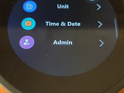
From the 'settings' menu select 'Admin'
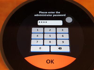
It will ask you for a pin code. I worked it out to 0018. I figured I'd start at 0000 and do 50 numbers each time until I found it. It took 18 goes.
Punch in 0018 - press OK.
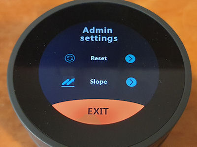
Here you have two options, one for resetting it and one for what looks like calibration.

The 'admin' reset is a full factory reset and will wipe the PDFs too.

The 'slope' menu. It looks like some kind of calibration menu - i suspect here be dragons.
And to AEG Test - If you had let me copy the manual, I may not have been so determined to pull your kit to bits. You might want to think that one out a bit harder next time!
Have at it people, and screw corporate lock-downs on user goods. I really support 'right to repair' and general documentation should be available for all for free. There may be more menus. Maybe at some point I'll try and download the firmware, have a poke about. Have a look for anything hidden, interesting.
All being well and if it works, my next post on this will be a mod to upload the results to your own server and from there you can do with the data what you want.
The manual states: “Admin: Technician access only (Note: Do Not Click.)”
Do not click?
On something I bought? Something I own?
Really?
Give me a big red button that says 'do not press,' and I’m going to press it.
If it’s locked behind a PIN code, I’m going to try and guess it.
And you, AEG Test — you’ve just fuelled me with the absolute determination to click things, crack things, push buttons and tear them to pieces.
That said — I still think this is a decent little unit.
So everyone deserves access to the admin menu.
Just be warned: there may be dragons. ?
From the 'settings' menu select 'Admin'
It will ask you for a pin code. I worked it out to 0018. I figured I'd start at 0000 and do 50 numbers each time until I found it. It took 18 goes.
Punch in 0018 - press OK.
Here you have two options, one for resetting it and one for what looks like calibration.
The 'admin' reset is a full factory reset and will wipe the PDFs too.
The 'slope' menu. It looks like some kind of calibration menu - i suspect here be dragons.
And to AEG Test - If you had let me copy the manual, I may not have been so determined to pull your kit to bits. You might want to think that one out a bit harder next time!
Have at it people, and screw corporate lock-downs on user goods. I really support 'right to repair' and general documentation should be available for all for free. There may be more menus. Maybe at some point I'll try and download the firmware, have a poke about. Have a look for anything hidden, interesting.
All being well and if it works, my next post on this will be a mod to upload the results to your own server and from there you can do with the data what you want.
Attachments:
Last edit: 1 year 1 month ago by Simomax.
Please Log in or Create an account to join the conversation.
1 year 1 month ago #7429
by jnissen
Replied by jnissen on topic AEGTest Hound-3699 Radon Monitor
You had me laughing out loud on the commentary for the admin mode. So stupid they would try to hide that from the users. Good job on the hack, only 18 tries!
The chamber is interesting. I agree on the IC's likely for HV generation and regulation. The lack of inductors or coils may mean the unit runs at significantly lower voltage. I see a potential for several stages of voltage doubling with the diodes and caps in that area. Still would not likely get high voltage.
I just noticed under that foam bit there appears to be traces running and that could be a larger coil for a flyback. Were you able to determine what is under that foam?
Overall a fascinating piece of gear. Would be very interested if you are going to tear down the chamber to see what is inside.
Please Log in or Create an account to join the conversation.
1 year 1 month ago - 1 year 1 month ago #7430
by Simomax
Replied by Simomax on topic AEGTest Hound-3699 Radon Monitor
That was a fun one to write up.

The Chamber.
I wasn't actually going to look into the chamber more, but since you ask nicely, and curiosity got the better of me I dug into it - and I'm glad I did! Quite interesting. A little, but not actually quite as I expected.
(I have added the high resolution images of this post to the download in the first post.)
Under the little metal cap on the underside of the chamber there are more discrete electronics and in the center a long gold plated pin that runs into the chamber. All the markings have been removed like the rest of the ICs. It would be very easy to copy this had the part numbers been intact. You could probably make one from a tin of beans, or two. Might not be quite as effective, but I reckon a home made version would be 90% of this bought one.
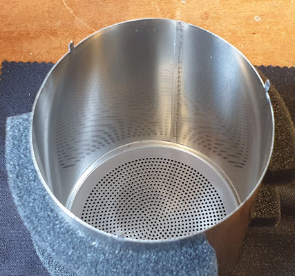
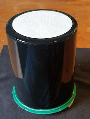
This is the (outer) can of the chamber, and here is where it starts to get interesting.
This is the inner can of the chamber. It looks identical to the outer can, but is covered with a plastic insulation and filter membrane at the top. Inside this (inner) can it looks identical to the outer can, but slightly smaller. I didn't measure it.
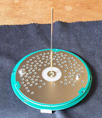
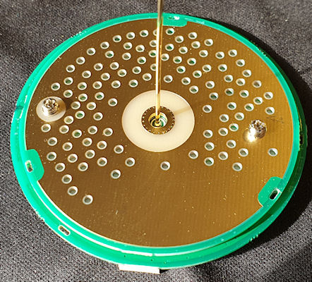
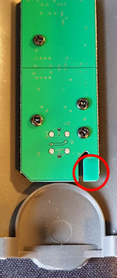
This is the base of the chamber with the long gold plated pin that is connected to the components under the little metal cap on the underside. If you look carefully at the gold plated PCB you can see that one screw is insulated, and the other isn't.
The base is actually two PCBs, sandwiched together with a filter membrane between. The holes in each PCB line up and allow air, or radon to pass through the filter membrane.
And this is where it all comes together. Firstly, I measured the voltage at 300v. Typical voltage for an ion chamber. But even with the tiny components this thing may be able to reach ~700v. I have a couple of counters with tiny HV PSUs like this, and they are quite capable up to around 700v. It may seem surprising, but you can easily get to a few hundred volts using voltage doublers from ~60v or so. Or even a very simple boost circuit, with a handful of components (switching transistor, inductor, capacitor, diode - literally just those 4 components) and run from a PWM signal can also quite easily get to ~700v. I have a counter right here with a PSU like that and I have pushed it to just under 900v, but it gets squiffy >780v.
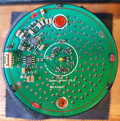
Anyway, back to this chamber. If you look at the image above (high resolution images are in the first post), you can see I have marked a black circle and solder pads, a red circle and solder pads, and also one of the screws, and the yellow dot in the center. The yellow dot is the gold plated pin. The black circle is the outer can, and is connected to ground. The red circle is the inner can, and this is connected to +300v, along with the gold plated side of the PCB. The gold plated PCB side is connected to +300v via one of the two screws. The other screw has an insulator on it. By connecting the inner can and the gold plated PCB part to +300v it is more-or-less completely surrounding the gold pin inside, then as the other PCB also has a ground plane on it, this and the outer can pretty much surround the whole inner can. It's a neat design, and seems to work quite well. I don't know what potential the center pin is as as I haven't probed it, but I have a feeling it may be floating - somewhere between +300v and ground. I don't fully understand how this chamber works and the center pin is quite the distance from the inner can. I have a feeling this may require the decay of radon to charge something (the space between the pin and the inner can?) and when it gets to a certain level it ionizes, passes a small current and creates the pulse. Much like a GM tube, but charges from multiple alpha particles (I think) and then completes the circuit, whereas a GM tube is one ionization, one pulse - much faster.
That's about it. And thanks jnissen for asking. I wouldn't have taken it apart had you not, and I wouldn't have discovered all of this radon detecting goodness!
The Chamber.
I wasn't actually going to look into the chamber more, but since you ask nicely, and curiosity got the better of me I dug into it - and I'm glad I did! Quite interesting. A little, but not actually quite as I expected.
(I have added the high resolution images of this post to the download in the first post.)
Under the little metal cap on the underside of the chamber there are more discrete electronics and in the center a long gold plated pin that runs into the chamber. All the markings have been removed like the rest of the ICs. It would be very easy to copy this had the part numbers been intact. You could probably make one from a tin of beans, or two. Might not be quite as effective, but I reckon a home made version would be 90% of this bought one.
This is the (outer) can of the chamber, and here is where it starts to get interesting.
This is the inner can of the chamber. It looks identical to the outer can, but is covered with a plastic insulation and filter membrane at the top. Inside this (inner) can it looks identical to the outer can, but slightly smaller. I didn't measure it.
This is the base of the chamber with the long gold plated pin that is connected to the components under the little metal cap on the underside. If you look carefully at the gold plated PCB you can see that one screw is insulated, and the other isn't.
The base is actually two PCBs, sandwiched together with a filter membrane between. The holes in each PCB line up and allow air, or radon to pass through the filter membrane.
And this is where it all comes together. Firstly, I measured the voltage at 300v. Typical voltage for an ion chamber. But even with the tiny components this thing may be able to reach ~700v. I have a couple of counters with tiny HV PSUs like this, and they are quite capable up to around 700v. It may seem surprising, but you can easily get to a few hundred volts using voltage doublers from ~60v or so. Or even a very simple boost circuit, with a handful of components (switching transistor, inductor, capacitor, diode - literally just those 4 components) and run from a PWM signal can also quite easily get to ~700v. I have a counter right here with a PSU like that and I have pushed it to just under 900v, but it gets squiffy >780v.
Anyway, back to this chamber. If you look at the image above (high resolution images are in the first post), you can see I have marked a black circle and solder pads, a red circle and solder pads, and also one of the screws, and the yellow dot in the center. The yellow dot is the gold plated pin. The black circle is the outer can, and is connected to ground. The red circle is the inner can, and this is connected to +300v, along with the gold plated side of the PCB. The gold plated PCB side is connected to +300v via one of the two screws. The other screw has an insulator on it. By connecting the inner can and the gold plated PCB part to +300v it is more-or-less completely surrounding the gold pin inside, then as the other PCB also has a ground plane on it, this and the outer can pretty much surround the whole inner can. It's a neat design, and seems to work quite well. I don't know what potential the center pin is as as I haven't probed it, but I have a feeling it may be floating - somewhere between +300v and ground. I don't fully understand how this chamber works and the center pin is quite the distance from the inner can. I have a feeling this may require the decay of radon to charge something (the space between the pin and the inner can?) and when it gets to a certain level it ionizes, passes a small current and creates the pulse. Much like a GM tube, but charges from multiple alpha particles (I think) and then completes the circuit, whereas a GM tube is one ionization, one pulse - much faster.
That's about it. And thanks jnissen for asking. I wouldn't have taken it apart had you not, and I wouldn't have discovered all of this radon detecting goodness!
Attachments:
Last edit: 1 year 1 month ago by Simomax.
Please Log in or Create an account to join the conversation.
1 year 1 month ago #7431
by Simomax
Replied by Simomax on topic AEGTest Hound-3699 Radon Monitor
***A note to anyone thinking of testing a radon detector with a hot(ish) U-238 source to generate radon.
Don't.
I have a small Fergusonite(Y) crystal pair (Yittrium ore). It is only 4.3 grams but really spicy and after a little testing and verifying it in fact does emit quite a lot of radon for it's mass. Lala (AI) decided to name it my 'little radon engine'. I thought I would use the Fergusonite to excite the radon detector into throwing out some pulses whilst I was probing about and I also stuffed the Fergusonite under the unit once I had reassembled it to verify it was working and also whilst I was using the pulses and programming an ESP - more later on this - if it works. It did well for testing, but sent the AEGTest 3699 nuts. It pinned some of the averages at 1227 Bq/m3, but the specs say the 3699 can go to 20,000 Bq/m3? but worse than that, it has contaminated the chamber with radon progeny, and won't reach equilibrium in fresh air. Last night it was showing about 40 Bq/m3 in fresh air, and today it is showing ~20 Bq/m3.
It does state this may happen in the manual - which I can't bloody show you cos, asses. Anyway, it states if in a really high radon area (= my desk with my little radon engine on it) it can take 24-48 hours to calm down, or even up to 3.8 days as that is the radon half-life. So I suspect in a couple of days it will be back to normal.
If anyone is going to use a U-238 source to generate radon - a lot of radon around a detector, it may make it squiffy for a few days!
Please Log in or Create an account to join the conversation.
Moderators: Gamma-Man
Time to create page: 0.340 seconds