
×
Discuss old and vintage Geiger counters and equipment. Please try to keep this to pre-1990's counters and other radiation related equipment from that era.
Super Sniffer! Could use an assist
1 year 10 months ago - 1 year 10 months ago #7020
by hotspider
Super Sniffer! Could use an assist was created by hotspider
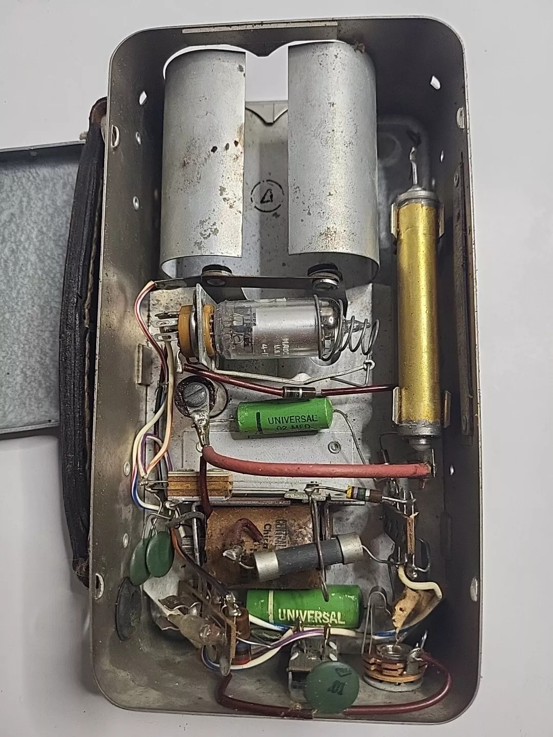
I recently acquired an old 1960's Chicago Nuclear Super Sniffer. It's pretty well intact, but not operating. Does anyone have experience with these? I'd like to restore it to operating condition.

Attachments:
Last edit: 1 year 10 months ago by hotspider. Reason: Image issues.
Please Log in or Create an account to join the conversation.
1 year 10 months ago - 1 year 10 months ago #7021
by Simomax
Replied by Simomax on topic Super Sniffer! Could use an assist
Interesting counter. I like it. I don't have one of these, but do have one of a similar vintage that has a similar high voltage power supply - a vibrator. I'll let you know what I can about this.
Some links to info:
https://orau.org/health-physics-museum/collection/survey-instruments/1950s/super-sniffer-geiger-counter.html
https://www.atomictourism.us/2022/08/02/model-2302-super-sniffer/
http://national-radiation-instrument-catalog.com/new_page_42.htm
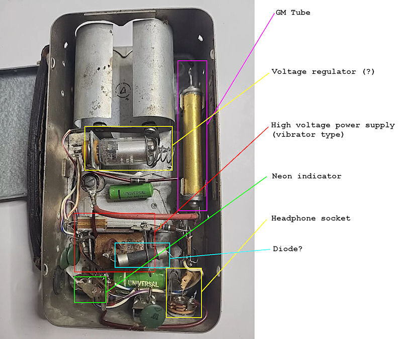
I have attached a (your) picture and indicated what I think are the parts inside.
Firstly, do you have the battery cover for this? If not you are going to have to either make a battery cover or hook up to an external battery holder, or a 1.5v (?) power supply. It is said to use 'flashlight' batteries so at a guess I would suggest 'D' size batteries, two of them. Looking at the battery contacts it seems they are meant to both go in the same way. Either both positives in together leaving the negatives towards the outside of the case, or could be the other way around. It's really hard to tell. I think the entire case is connected to the 'other end' of the batteries as there appears no other battery terminals. On the opposite end to the batteries are the on/off switch and headphone socket. This doesn't have a built in speaker so clicks can only be heard with headphones. It looks like a regular 6.3mm mono jack socket, so modern headphones may work, but only one one channel. Impedance of the headphones may be a problem if too low. Most common headphones are around 33 ohms (you can get them up to around 600 ohms but 33 is most common) and this may be a bit low for the counter to hear the clicks loudly. It looks like the ground for the headphones is connected to the metal case and the signal is via the small green disc capacitor that connects on the solder tab strip at the lower left (in your picture). There is also a neon indicator which I believe should light when pulses are detected from the GM tube.
The high voltage is generated by a 'vibrator'. This is similar to a modern boost circuit but the vibrator creates the magnetic field electro-mechanically. When the counter is powered on a buzzing (vibrating) should be heard and you should see the contacts on the vibrator vibrating at a high speed. This web page explains how they work better than I could so is well worth a read. I think, but not certain, that once the high voltage is generated from the vibrator this then goes to the voltage regulator (the vacuum tube) and then goes to the GM tube. I can't say much for the detection circuit as I'm not familiar with this counter and can't find any circuit diagram. The big green things with 'Universal' printed on them are capacitors. I'm unsure what the grey cylindrical 'fuse' looking thing is. Maybe a diode?
In a nutshell you are going to want to get something figured out with the batteries if you haven't got the battery cover. Once you have batteries attached you should hear a buzzing coming from the vibrator. If you don't hear buzzing then you have a power supply/vibrator issue. Vintage vibrators had many issues and were generally quite unreliable after a time of usage. Some common things are dirty/corroded/misaligned contacts, insulation break down of the coil(s), moisture ingress causing internal leakage. If your vibrator is working you should get a fair voltage on the GM tube, provided the regulator is working, and these are also quite prone to failure after some time. The current generated by the high voltage power supply will most likely be substantially higher than modern electronic counters, so be careful where you put your fingers if you get this working. It's not going to hurt, but may be enough of a surprise that you may drop the counter. This should also allow you to use a 20 M ohm multimeter to get an approx voltage. Without knowing what the GM tube is I have no idea what the voltage should be, but I would approximate no less than 400v and no more than 1000v.
Some links to info:
https://orau.org/health-physics-museum/collection/survey-instruments/1950s/super-sniffer-geiger-counter.html
https://www.atomictourism.us/2022/08/02/model-2302-super-sniffer/
http://national-radiation-instrument-catalog.com/new_page_42.htm
I have attached a (your) picture and indicated what I think are the parts inside.
Firstly, do you have the battery cover for this? If not you are going to have to either make a battery cover or hook up to an external battery holder, or a 1.5v (?) power supply. It is said to use 'flashlight' batteries so at a guess I would suggest 'D' size batteries, two of them. Looking at the battery contacts it seems they are meant to both go in the same way. Either both positives in together leaving the negatives towards the outside of the case, or could be the other way around. It's really hard to tell. I think the entire case is connected to the 'other end' of the batteries as there appears no other battery terminals. On the opposite end to the batteries are the on/off switch and headphone socket. This doesn't have a built in speaker so clicks can only be heard with headphones. It looks like a regular 6.3mm mono jack socket, so modern headphones may work, but only one one channel. Impedance of the headphones may be a problem if too low. Most common headphones are around 33 ohms (you can get them up to around 600 ohms but 33 is most common) and this may be a bit low for the counter to hear the clicks loudly. It looks like the ground for the headphones is connected to the metal case and the signal is via the small green disc capacitor that connects on the solder tab strip at the lower left (in your picture). There is also a neon indicator which I believe should light when pulses are detected from the GM tube.
The high voltage is generated by a 'vibrator'. This is similar to a modern boost circuit but the vibrator creates the magnetic field electro-mechanically. When the counter is powered on a buzzing (vibrating) should be heard and you should see the contacts on the vibrator vibrating at a high speed. This web page explains how they work better than I could so is well worth a read. I think, but not certain, that once the high voltage is generated from the vibrator this then goes to the voltage regulator (the vacuum tube) and then goes to the GM tube. I can't say much for the detection circuit as I'm not familiar with this counter and can't find any circuit diagram. The big green things with 'Universal' printed on them are capacitors. I'm unsure what the grey cylindrical 'fuse' looking thing is. Maybe a diode?
In a nutshell you are going to want to get something figured out with the batteries if you haven't got the battery cover. Once you have batteries attached you should hear a buzzing coming from the vibrator. If you don't hear buzzing then you have a power supply/vibrator issue. Vintage vibrators had many issues and were generally quite unreliable after a time of usage. Some common things are dirty/corroded/misaligned contacts, insulation break down of the coil(s), moisture ingress causing internal leakage. If your vibrator is working you should get a fair voltage on the GM tube, provided the regulator is working, and these are also quite prone to failure after some time. The current generated by the high voltage power supply will most likely be substantially higher than modern electronic counters, so be careful where you put your fingers if you get this working. It's not going to hurt, but may be enough of a surprise that you may drop the counter. This should also allow you to use a 20 M ohm multimeter to get an approx voltage. Without knowing what the GM tube is I have no idea what the voltage should be, but I would approximate no less than 400v and no more than 1000v.
Attachments:
Last edit: 1 year 10 months ago by Simomax.
The following user(s) said Thank You: GuzzoTheLuke
Please Log in or Create an account to join the conversation.
1 year 10 months ago #7022
by hotspider
Replied by hotspider on topic Super Sniffer! Could use an assist
A member of an antique geiger counter group on Facebook pointed me to a manual and schematic for this on eBay. I've ordered it. Will post anything useful in it here.
Thank you for the break-down.
Chis
Thank you for the break-down.
Chis
The following user(s) said Thank You: GuzzoTheLuke
Please Log in or Create an account to join the conversation.
Time to create page: 0.194 seconds