
HFS-P3 Pen Geiger Counter / Dosimeter
3 years 7 months ago - 3 years 1 month ago #6313
by Simomax
HFS-P3 Pen Geiger Counter / Dosimeter was created by Simomax
HFS-P3 Pen type pocket geiger counter / dosimeter
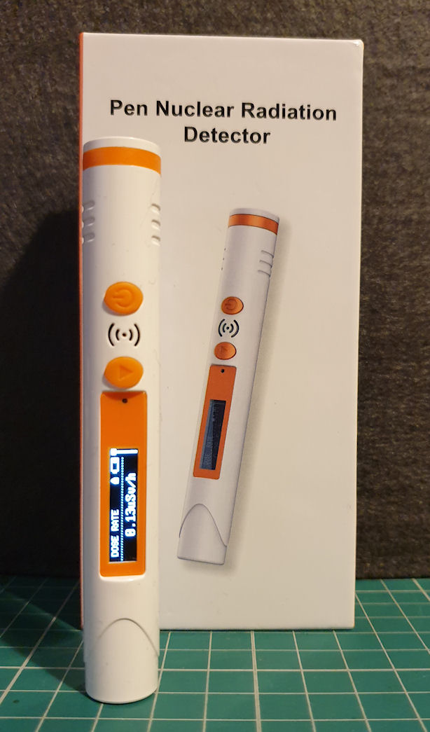
I have seen these kicking around the usual suspects (Ebay, Amazon, Aliexpress etc.) for a little while now and after watching (a not very informative YouTube video) I decided to get one and see just what it is and is it any good. TLDR; You get what you pay for.
I paid about £32 for this from Aliexpress.com but have seen them for as little as £25 on Aliexpress.com and as high as £60 on Ebay and Amazon.
The unit is very small and packs a tiny 150mAh LiPo cell, 48mm x 7mm (external dimensions) HH614 GM Tube, tiny OLED screen, a massive overkill ARM Cortex-M0 FM33LC043N MCU from Fudan Micro and all the supporting electronics. The unit is pretty well made for it's price point, though I suspect these have been manufactured in their tens of thousands, and in China, bigger production runs really keep prices down. It is fairly easy to get apart but does require either a pair of needle-nose pliers or some finesse to pull the board out of it's case. These appear to be a generic item, made by one manufacturer and sold under many different brands, although the model HFS-P3 seems to be the same with all brands. I think the manufacturer may be MUFASHA or this could be just another brand name. I contacted them for details on the GM tube (spec sheet etc) but their reply was just the specs in the manual. They never replied to my second email asking for further information. I think they were more bothered about where I had purchased it from.
Technical specs (manufacturer)
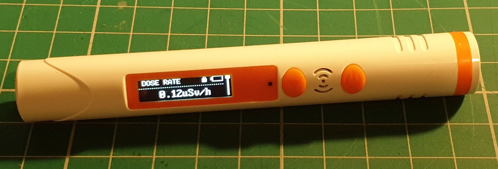
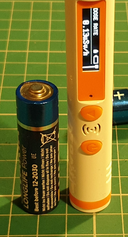
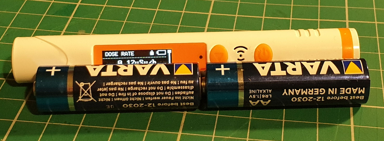
The unit small measuring in at just 108mm long by 15mm diameter. Below you can see it next to a couple of AA batteries for size comparison. It has a handy clip for clipping it to things, a couple of buttons for powering on/off and using the (limited) menu.
On the inside we see that the board is quite nicely laid out with the HV stage as far away from the MCU and other electronics, although quite close to the OLED screen. Everything, whilst soldered, is just stuck to the board with double-sided sticky tape, which is quite common these days, and reflects in the price point. The adhesion should be good for 10-20 years, way longer than the battery would last.
Here we see the HH614 GM 48x7mm GM tube
Here looks to be the switching IC sandwiched under the OLED screen for the HV PSU
The unit's features are limited. It sports 4 modes of operation (dose rate, accumulated dose, average dose and max dose rate) with a two configurable alarms for dose rate and accumulated dose, and that is it. Nothing more, nothing less. The only user settings are the two alarm thresholds. It has an internal sounder for the alarm but seems to not work as a clicker for the detected pulses. Probably a good thing as the battery life is terrible. It states in the manual that the unit will last 50 hours between recharges, and it kinda does, if you never use the screen! In testing I was getting about 10 hours from a full charge when displaying the screen every half hour or so. When I tested further and only displayed the screen three times or so, it lasted about 45 hours. So I could see it getting 50 hours, at a real push without displaying the screen at all. This means the OLED screen is consuming a massive amount of the available capacity from the LiPo battery. The screen is super bright too and could be used at half the luminance. It also stays on for way too long. It is something like a minute or two before it turns off. If displayed for only 15 seconds or so this would have much less impact on battery life. The battery takes approximately 3 hours to charge fully using any charger. There was no difference between a 500ma charger or a 15w USB-C fast charger. The internal BMS/charge circuit will limit the current to the battery under charging. It looks to be hackable and the pulses from the detector circuit go right into the MCU, so should be able to pull off a (3.3v?) pulse from the board somewhere, and feed that into Arduino or something. Removing the battery and powering from an external PSU would work to be able to power this for long periods. I wouldn't want to keep the battery on board though and have it powered externally for a long period as the BMS/charger could get squiffy and blow the battery up. Remember this is made from fine Chineseium!
When using the unit operates as you would expect. It detects radiation, counts up a dose rate and accumulated dose, will trigger an alarm if the threshold is reached. The different modes can be selected by a single button press to scroll through the 4 modes. In order to set the alarm thresholds the unit must be 'unlocked' by holding the menu button down and pressing the power button simultaneously and then using the menu key to access the alarm settings in the same way of accessing the other modes. One downside is that once the unit is powered off the accumulated dose resets to 0. So in order to use this as a personal dosimeter it will have to be recharged mid way if the length of time used if this time is more than the battery life in order to retain the accumulated dose.
The tube is interesting and I really struggled to find any info on it. It is labeled HH614. I managed to find a similar tube the J614y ( see here , and here ) that fits the size and physical look of the tube, but there are some small differences such as the white insulators inside the tube. I suspect the HH614 may be a copy of the J614y. In testing I found this to be not so sensitive, and would estimate this to be about half the sensitivity of the J305b or M4011 at roughly 10 CPM background. In searching for this tube (and I did search, oh man, did I search) I discovered that the last character on these Chinese tubes refers to the radiation type the tube is designed to detect. For instance, the J605b is designed more for beta, and the J614y is designed more for gamma. It kinda makes sense!
Here are the specs for the J614y, which is very similar to the HH614, and as I have nothing more solid, I'm going to go with these specs as an approximation of the HH614.
Pros:
Small and light weight. Easy to navigate menus. Clear display. Works as intended. Looks to be hackable (somewhat).
Cons:
Poor battery life. Limited features. Dose accumulation resets when powered off. Low lifespan of the product, due to it's internal battery. Uses a MCU with far more capability than the unit has been given. No warning when the battery is nearly empty - it just reaches a level and turns off.
Conclusion:
A fine product to give a child as their first Geiger counter. Don't give it to a child too young though as it could be a choking hazard! It does what it says. The battery life is miserable and once the battery reaches end of life you will have a plastic tube with some electronic gubbins (providing it doesn't burst into flames!). The MCU has loads of features that could have been made use of. It has 256Kb flash memory, 24Kb RAM, 9 channel 12 bit ADC, 6 UARTs, operates from 4-64MHz, On-chip temperature sensor, Real-Time Clock, WDT, Hardware Cryptographic Engine, TRNG, PWM, Low-VoltageDetect, CCP capture/compare. Loads of features (some I don't even know what they are) and about 1% of the MCU is being used. It could have been programmable by way of UART/USB, and have some data pushed out over UART/USB, such as chucking out the CPM every second or something. With all the horsepower of the CPU it could have been made so much better. It could store the accumulated dose in flash memory when powered down, displayed CPM, maybe CPS, sounded the on-board sounder as a clicker, logged events to flash, even logged every sample into flash for download later. It could have had a warning when the battery level is low. It could have displayed the temperature, It could have a configurable timer and brightness for the OLED screen... And they are just the things at the top of my mind.
In short, not a serious counter. I wouldn't use it for anything more than shits and giggles, or maybe a child's first Geiger counter - but the lack of a clicker would make it boring very fast for anyone, child or adult! It could have been so much better with just better software implementation, it has the MCU capacity, but the battery life is the real crux of it all.
Finally, here is the (Chinglish) manual for anyone interested:
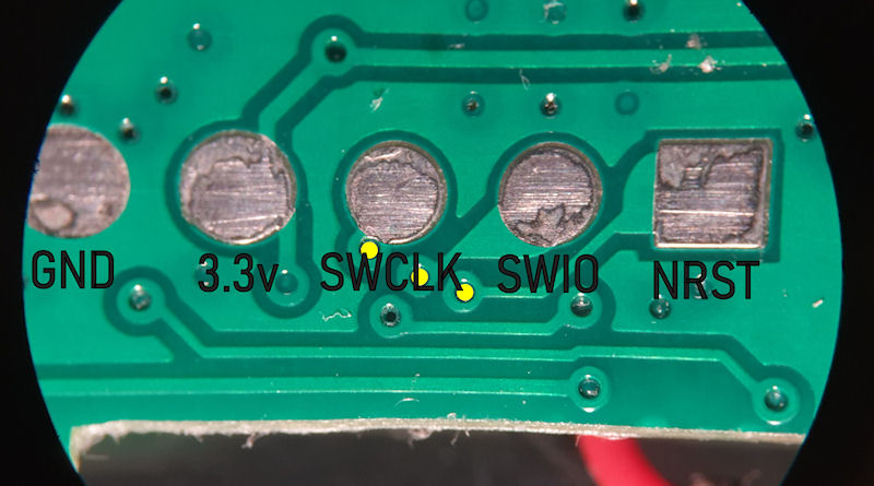
This is my favourite part (in safety notices):

I have seen these kicking around the usual suspects (Ebay, Amazon, Aliexpress etc.) for a little while now and after watching (a not very informative YouTube video) I decided to get one and see just what it is and is it any good. TLDR; You get what you pay for.
I paid about £32 for this from Aliexpress.com but have seen them for as little as £25 on Aliexpress.com and as high as £60 on Ebay and Amazon.
The unit is very small and packs a tiny 150mAh LiPo cell, 48mm x 7mm (external dimensions) HH614 GM Tube, tiny OLED screen, a massive overkill ARM Cortex-M0 FM33LC043N MCU from Fudan Micro and all the supporting electronics. The unit is pretty well made for it's price point, though I suspect these have been manufactured in their tens of thousands, and in China, bigger production runs really keep prices down. It is fairly easy to get apart but does require either a pair of needle-nose pliers or some finesse to pull the board out of it's case. These appear to be a generic item, made by one manufacturer and sold under many different brands, although the model HFS-P3 seems to be the same with all brands. I think the manufacturer may be MUFASHA or this could be just another brand name. I contacted them for details on the GM tube (spec sheet etc) but their reply was just the specs in the manual. They never replied to my second email asking for further information. I think they were more bothered about where I had purchased it from.
Technical specs (manufacturer)
- Sensor: 48mm Geiger counter tube
- Measure range: 0.08uSv - 50mSv
- Measure precision: -17%...+25% based on Cs-137 y
- Working environment: temperature -20°C...50°C; humidity <95% RH without dew
- size: diameter 15.3mm, length 108mm, weight 19g
- Durable time: 50Hour (continue measure, screen dormant)
- Charging time: 2-3 hours
- Charging joggle: TYPE-C joggle (green light normally lighting when charging, extincted when fully charged)
- Alarm responding time td: <10s
The unit small measuring in at just 108mm long by 15mm diameter. Below you can see it next to a couple of AA batteries for size comparison. It has a handy clip for clipping it to things, a couple of buttons for powering on/off and using the (limited) menu.
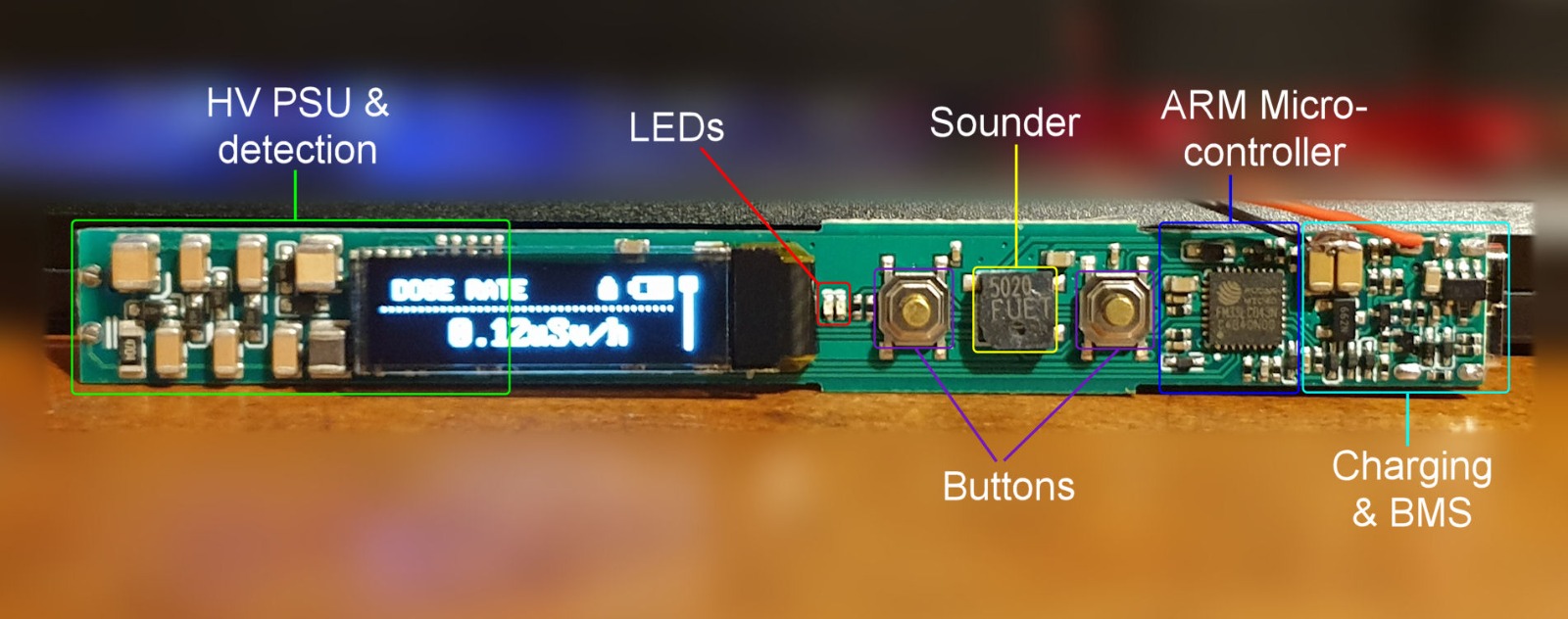
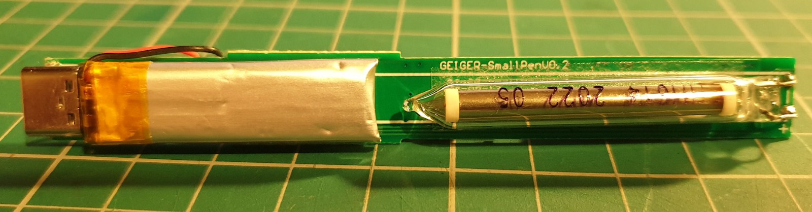
On the inside we see that the board is quite nicely laid out with the HV stage as far away from the MCU and other electronics, although quite close to the OLED screen. Everything, whilst soldered, is just stuck to the board with double-sided sticky tape, which is quite common these days, and reflects in the price point. The adhesion should be good for 10-20 years, way longer than the battery would last.
Here we see the HH614 GM 48x7mm GM tube
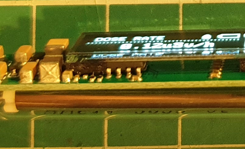
Here looks to be the switching IC sandwiched under the OLED screen for the HV PSU
The unit's features are limited. It sports 4 modes of operation (dose rate, accumulated dose, average dose and max dose rate) with a two configurable alarms for dose rate and accumulated dose, and that is it. Nothing more, nothing less. The only user settings are the two alarm thresholds. It has an internal sounder for the alarm but seems to not work as a clicker for the detected pulses. Probably a good thing as the battery life is terrible. It states in the manual that the unit will last 50 hours between recharges, and it kinda does, if you never use the screen! In testing I was getting about 10 hours from a full charge when displaying the screen every half hour or so. When I tested further and only displayed the screen three times or so, it lasted about 45 hours. So I could see it getting 50 hours, at a real push without displaying the screen at all. This means the OLED screen is consuming a massive amount of the available capacity from the LiPo battery. The screen is super bright too and could be used at half the luminance. It also stays on for way too long. It is something like a minute or two before it turns off. If displayed for only 15 seconds or so this would have much less impact on battery life. The battery takes approximately 3 hours to charge fully using any charger. There was no difference between a 500ma charger or a 15w USB-C fast charger. The internal BMS/charge circuit will limit the current to the battery under charging. It looks to be hackable and the pulses from the detector circuit go right into the MCU, so should be able to pull off a (3.3v?) pulse from the board somewhere, and feed that into Arduino or something. Removing the battery and powering from an external PSU would work to be able to power this for long periods. I wouldn't want to keep the battery on board though and have it powered externally for a long period as the BMS/charger could get squiffy and blow the battery up. Remember this is made from fine Chineseium!
When using the unit operates as you would expect. It detects radiation, counts up a dose rate and accumulated dose, will trigger an alarm if the threshold is reached. The different modes can be selected by a single button press to scroll through the 4 modes. In order to set the alarm thresholds the unit must be 'unlocked' by holding the menu button down and pressing the power button simultaneously and then using the menu key to access the alarm settings in the same way of accessing the other modes. One downside is that once the unit is powered off the accumulated dose resets to 0. So in order to use this as a personal dosimeter it will have to be recharged mid way if the length of time used if this time is more than the battery life in order to retain the accumulated dose.
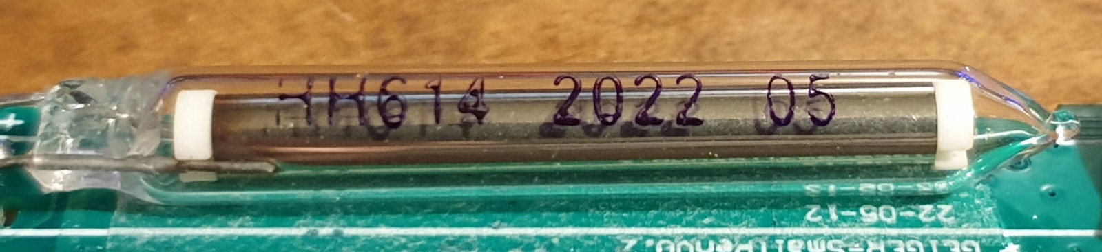
The tube is interesting and I really struggled to find any info on it. It is labeled HH614. I managed to find a similar tube the J614y ( see here , and here ) that fits the size and physical look of the tube, but there are some small differences such as the white insulators inside the tube. I suspect the HH614 may be a copy of the J614y. In testing I found this to be not so sensitive, and would estimate this to be about half the sensitivity of the J305b or M4011 at roughly 10 CPM background. In searching for this tube (and I did search, oh man, did I search) I discovered that the last character on these Chinese tubes refers to the radiation type the tube is designed to detect. For instance, the J605b is designed more for beta, and the J614y is designed more for gamma. It kinda makes sense!
Here are the specs for the J614y, which is very similar to the HH614, and as I have nothing more solid, I'm going to go with these specs as an approximation of the HH614.
- Cathode Material: Stainless Steel
- Anode Material: Tungsten
- Construction: Glass Envelope
- Max. Length: 55mm (2.2”)
- Maximum Diameter: 7.5mm (0.313”)
- Recommended Anode Resistor: 5m
- Starting Voltage: 330v
- Recommended Operating Voltage: 400v
- Operating Voltage Range: 380v-460v
- Sensitivity: Gamma, Beta, and X-Rays
- Lifetime: 1 x 10¹⁰ (10 billion /1902 years at background CPM)
- Background CPM: 10 (Los Angeles/Southern California area)
Pros:
Small and light weight. Easy to navigate menus. Clear display. Works as intended. Looks to be hackable (somewhat).
Cons:
Poor battery life. Limited features. Dose accumulation resets when powered off. Low lifespan of the product, due to it's internal battery. Uses a MCU with far more capability than the unit has been given. No warning when the battery is nearly empty - it just reaches a level and turns off.
Conclusion:
A fine product to give a child as their first Geiger counter. Don't give it to a child too young though as it could be a choking hazard! It does what it says. The battery life is miserable and once the battery reaches end of life you will have a plastic tube with some electronic gubbins (providing it doesn't burst into flames!). The MCU has loads of features that could have been made use of. It has 256Kb flash memory, 24Kb RAM, 9 channel 12 bit ADC, 6 UARTs, operates from 4-64MHz, On-chip temperature sensor, Real-Time Clock, WDT, Hardware Cryptographic Engine, TRNG, PWM, Low-VoltageDetect, CCP capture/compare. Loads of features (some I don't even know what they are) and about 1% of the MCU is being used. It could have been programmable by way of UART/USB, and have some data pushed out over UART/USB, such as chucking out the CPM every second or something. With all the horsepower of the CPU it could have been made so much better. It could store the accumulated dose in flash memory when powered down, displayed CPM, maybe CPS, sounded the on-board sounder as a clicker, logged events to flash, even logged every sample into flash for download later. It could have had a warning when the battery level is low. It could have displayed the temperature, It could have a configurable timer and brightness for the OLED screen... And they are just the things at the top of my mind.
In short, not a serious counter. I wouldn't use it for anything more than shits and giggles, or maybe a child's first Geiger counter - but the lack of a clicker would make it boring very fast for anyone, child or adult! It could have been so much better with just better software implementation, it has the MCU capacity, but the battery life is the real crux of it all.
Finally, here is the (Chinglish) manual for anyone interested:
This is my favourite part (in safety notices):
Attachments:
Last edit: 3 years 1 month ago by Simomax.
The following user(s) said Thank You: manuelgomez1, jonah10242
Please Log in or Create an account to join the conversation.
3 years 4 days ago #6521
by Simomax
Replied by Simomax on topic HFS-P3 Pen Geiger Counter / Dosimeter
I was asked by Gissio to try and download the original firmware from my HFS-P3, so I tried. Alas, no joy so far.
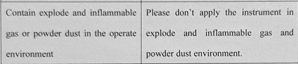
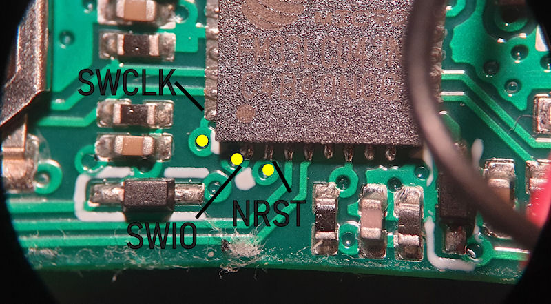
 Under the battery (stuck down with sticky tape) is a pin header. Probably designed to have a pogo pin connector connect to it as there is no room to solder on an actual pin header. I just soldered wires to it directly. I managed to work out the pins by tracing the circuit, but I had to use my microscope as the connections on the MCU really are that small! I took photos of both sides and flipped one then overlaied one over the other so I could line up the vias on the board. You can see in the pictures. Below is what I believe to be the correct pinout going from the datasheet of the MCU.
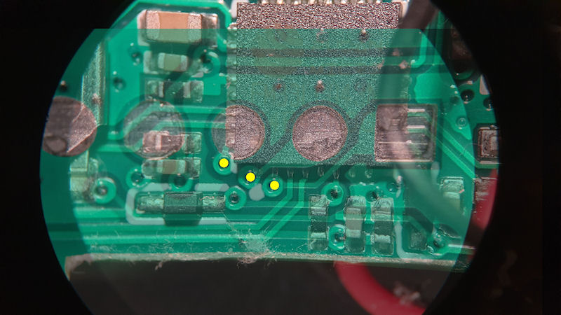
The instructions Gissio gave me was to do pretty much exactly the same as for the FS2011. I may need to connect +3.3v, but do this for as short time as possible. For some reason it just won't read the MCU. Maybe I got the pins wrong? The messages from ST Link are below. I have tried with just GND, SWIO and SWCLK, with and without +3.3v connected. I have tried in it's off state with +3.3v applied and also tried in various iterations with the NRST held low, and connected to RST on the ST LINK dongle. All with no joy.
The main message that kept coming back from the ST Link software was 'connect under reset'
The error about "The following device has no driver: 'USB\VID_2E8A&PID_000A&MI_02\7&2C249F46&0&0002'" can safely be ignored as I apparently have a device on my PC that has no driver. Not sure what this is (something with my PC) but nothing to do with ST Link.
Maybe Gissio or someone else can advise on this?
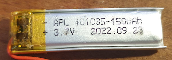
I also got a picture of the battery of the HFS-P3 whilst it was apart. A tiny 150mAh lipo cell.
The instructions Gissio gave me was to do pretty much exactly the same as for the FS2011. I may need to connect +3.3v, but do this for as short time as possible. For some reason it just won't read the MCU. Maybe I got the pins wrong? The messages from ST Link are below. I have tried with just GND, SWIO and SWCLK, with and without +3.3v connected. I have tried in it's off state with +3.3v applied and also tried in various iterations with the NRST held low, and connected to RST on the ST LINK dongle. All with no joy.
The main message that kept coming back from the ST Link software was 'connect under reset'
D:\stlink\bin>st-flash read backup.bin 0x08000000 0x10000
st-flash 1.7.0
libusb: info [winusb_get_device_list] The following device has no driver: 'USB\VID_2E8A&PID_000A&MI_02\7&2C249F46&0&0002'
libusb: info [winusb_get_device_list] libusb will not be able to access it
[!] send_recv read reply failed: LIBUSB_ERROR_PIPE
[!] send_recv STLINK_DEBUG_READCOREID
2023-07-12T08:36:33 ERROR common.c: Failed to read core_id
[!] send_recv read reply failed: LIBUSB_ERROR_PIPE
[!] send_recv STLINK_JTAG_READDEBUG_32BIT
2023-07-12T08:36:33 ERROR common.c: Can not connect to target. Please use 'connect under reset' and try again
Failed to connect to target
The error about "The following device has no driver: 'USB\VID_2E8A&PID_000A&MI_02\7&2C249F46&0&0002'" can safely be ignored as I apparently have a device on my PC that has no driver. Not sure what this is (something with my PC) but nothing to do with ST Link.
Maybe Gissio or someone else can advise on this?
I also got a picture of the battery of the HFS-P3 whilst it was apart. A tiny 150mAh lipo cell.
Attachments:
The following user(s) said Thank You: jonah10242
Please Log in or Create an account to join the conversation.

2 years 11 months ago - 2 years 11 months ago #6538
by gissio
Replied by gissio on topic HFS-P3 Pen Geiger Counter / Dosimeter
I just saw your message. Nice work!
Make sure NRST is connected. Then try this:
st-info.exe --probe --connect-under-reset
If it works, try the following (make sure the address 0x00000000 and size 0x40000 are correct):
st-flash.exe --connect-under-reset read backup.bin 0x00000000 0x40000
If it doesn't work, then most likely it won't be possible to get the firmware.
Last edit: 2 years 11 months ago by gissio.
Please Log in or Create an account to join the conversation.
2 years 8 months ago - 2 years 8 months ago #6729
by Simomax
Replied by Simomax on topic HFS-P3 Pen Geiger Counter / Dosimeter
I finally got around to looking at this again, but sadly, still no joy. I'm not sure if it something with my setup or just can't be done. It did work with the FS2100 though. The output below makes little sense to me. I even went back to the datasheet to verify the connections were correct, and does seem so.
D:\stlink\bin>st-info.exe --probe --connect-under-reset
[!] send_recv read reply failed: LIBUSB_ERROR_PIPE
[!] send_recv STLINK_JTAG_WRITEDEBUG_32BIT
[!] send_recv read reply failed: LIBUSB_ERROR_PIPE
[!] send_recv STLINK_JTAG_READDEBUG_32BIT
[!] send_recv read reply failed: LIBUSB_ERROR_PIPE
[!] send_recv STLINK_JTAG_READDEBUG_32BIT
[!] send_recv read reply failed: LIBUSB_ERROR_PIPE
[!] send_recv STLINK_JTAG_WRITEDEBUG_32BIT
[!] send_recv read reply failed: LIBUSB_ERROR_PIPE
[!] send_recv STLINK_JTAG_WRITEDEBUG_32BIT
[!] send_recv read reply failed: LIBUSB_ERROR_PIPE
[!] send_recv STLINK_JTAG_WRITEDEBUG_32BIT
[!] send_recv read reply failed: LIBUSB_ERROR_PIPE
[!] send_recv STLINK_JTAG_READDEBUG_32BIT
[!] send_recv read reply failed: LIBUSB_ERROR_PIPE
[!] send_recv STLINK_JTAG_WRITEDEBUG_32BIT
[!] send_recv read reply failed: LIBUSB_ERROR_PIPE
[!] send_recv STLINK_DEBUG_READCOREID
[!] send_recv read reply failed: LIBUSB_ERROR_PIPE
[!] send_recv STLINK_JTAG_READDEBUG_32BIT
Found 1 stlink programmers
  version:    V2J29S7
  serial:     360036002933353739303541
  flash:      0 (pagesize: 0)
  sram:       0
  chipid:     0x0000
  descr:      unknown device
D:\stlink\bin>st-flash.exe --connect-under-reset read backup.bin 0x00000000 0x40000
st-flash 1.7.0
libusb: info [winusb_get_device_list] The following device has no driver: 'USB\VID_2E8A&PID_000A&MI_02\7&2C249F46&0&0002'
libusb: info [winusb_get_device_list] libusb will not be able to access it
[!] send_recv read reply failed: LIBUSB_ERROR_PIPE
[!] send_recv STLINK_JTAG_WRITEDEBUG_32BIT
[!] send_recv read reply failed: LIBUSB_ERROR_PIPE
[!] send_recv STLINK_JTAG_READDEBUG_32BIT
[!] send_recv read reply failed: LIBUSB_ERROR_PIPE
[!] send_recv STLINK_JTAG_READDEBUG_32BIT
2023-10-16T18:11:16 WARN common.c: NRST is not connected
[!] send_recv read reply failed: LIBUSB_ERROR_PIPE
[!] send_recv STLINK_JTAG_WRITEDEBUG_32BIT
[!] send_recv read reply failed: LIBUSB_ERROR_PIPE
[!] send_recv STLINK_JTAG_WRITEDEBUG_32BIT
[!] send_recv read reply failed: LIBUSB_ERROR_PIPE
[!] send_recv STLINK_JTAG_WRITEDEBUG_32BIT
[!] send_recv read reply failed: LIBUSB_ERROR_PIPE
[!] send_recv STLINK_JTAG_READDEBUG_32BIT
[!] send_recv read reply failed: LIBUSB_ERROR_PIPE
[!] send_recv STLINK_JTAG_WRITEDEBUG_32BIT
2023-10-16T18:11:16 ERROR common.c: Soft reset failed: error write to AIRCR
[!] send_recv read reply failed: LIBUSB_ERROR_PIPE
[!] send_recv STLINK_DEBUG_READCOREID
2023-10-16T18:11:16 ERROR common.c: Failed to read core_id
[!] send_recv read reply failed: LIBUSB_ERROR_PIPE
[!] send_recv STLINK_JTAG_READDEBUG_32BIT
2023-10-16T18:11:16 ERROR common.c: Can not connect to target. Please use 'connect under reset' and try again
Failed to connect to target
Last edit: 2 years 8 months ago by Simomax.
Please Log in or Create an account to join the conversation.
- jonah10242
-

- Offline
- New Member
-

Less
More
- Posts: 4
- Thank you received: 1
2 years 1 month ago - 2 years 1 month ago #6997
by jonah10242
Replied by jonah10242 on topic HFS-P3 Pen Geiger Counter / Dosimeter
Greetings!
I was really intrigued by this device a while ago, considering its small form factor and price, and recently I had some time to look into it again.
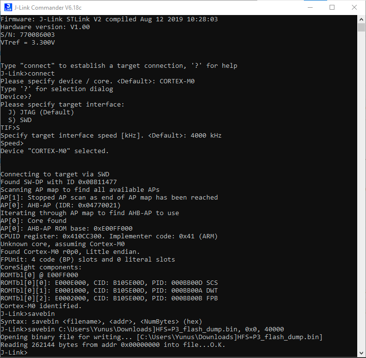
Reading through this post I feared the SWD was protected, fortunately that is not true and I successfully managed to enter debug mode and dump the entire flash to file.
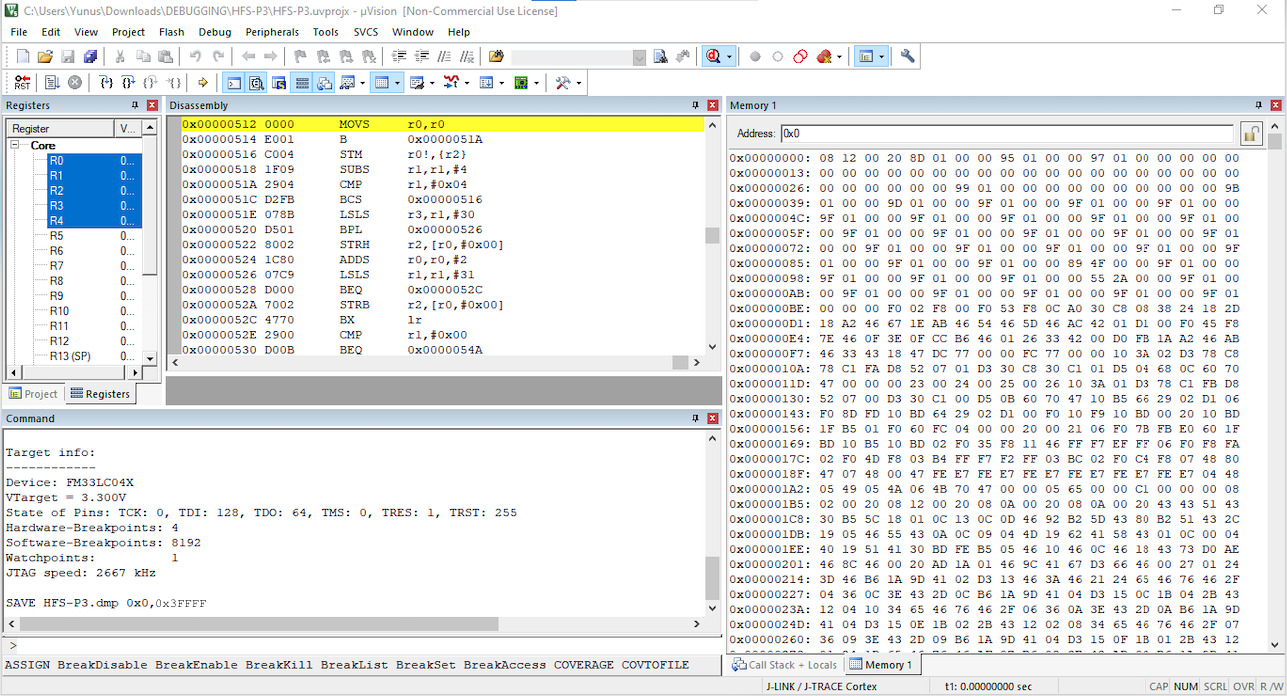
I used a J-Link device (actually a ST-Link V2 clone flashed with J-Link using STLinkReflash *) and I managed to dump it with J-Link Commander V6.18c as well as with Keil µVision V5 . Seeing above that st-flash.exe software did not work I did not bother trying that again.
For J-Link Commander I dumped it with
For Keil µVision V5 I dumped it with
Then converted the Intel HEX-386 file format to binary using hex2bin.exe
I also updated the GitHub issue of the RadPro custom firmware for better visibility but we'll have to see if someone with more coding experience would be interested enough to build something more useful than stock firmware for this device.
This chip is not as well documented as the STM32 series but I found some project/code examples for this FM33LC0xx that could be of help:
See the attached flash dump and here a newer English Datasheet for the FM33LC0xx
* Chinese clones that are not STM32 based need this mod instead
I was really intrigued by this device a while ago, considering its small form factor and price, and recently I had some time to look into it again.
Reading through this post I feared the SWD was protected, fortunately that is not true and I successfully managed to enter debug mode and dump the entire flash to file.
I used a J-Link device (actually a ST-Link V2 clone flashed with J-Link using STLinkReflash *) and I managed to dump it with J-Link Commander V6.18c as well as with Keil µVision V5 . Seeing above that st-flash.exe software did not work I did not bother trying that again.
For J-Link Commander I dumped it with
savebin C:\Users\jonah\Downloads\HFS-P3_dump.bin, 0x0, 40000
Warning: Spoiler!
For Keil µVision V5 I dumped it with
SAVE C:\Users\jonah\Downloads\HFS-P3_dump.hex 0x0,0x3FFFF
Warning: Spoiler!
Then converted the Intel HEX-386 file format to binary using hex2bin.exe
I also updated the GitHub issue of the RadPro custom firmware for better visibility but we'll have to see if someone with more coding experience would be interested enough to build something more useful than stock firmware for this device.
This chip is not as well documented as the STM32 series but I found some project/code examples for this FM33LC0xx that could be of help:
See the attached flash dump and here a newer English Datasheet for the FM33LC0xx
* Chinese clones that are not STM32 based need this mod instead
Attachments:
Last edit: 2 years 1 month ago by jonah10242.
The following user(s) said Thank You: Simomax
Please Log in or Create an account to join the conversation.
- jonah10242
-
- Offline
- New Member
-
Less
More
- Posts: 4
- Thank you received: 1
1 year 11 months ago - 1 year 11 months ago #7010
by jonah10242
Replied by jonah10242 on topic HFS-P3 Pen Geiger Counter / Dosimeter
[UPDATE]
Hello, it's me again.
I'm back with some updates regarding this device. I finally managed to reverse engineer the hardware part. I traced a schematic, gathered some really useful resources (suprisingly very well documented, once you find the right resources and use the correct language
 ) and built a base "proof of concept" Keil uVision IDE project that currently can control the the LEDS, buzzer, OLED and respond to buttons. Right now I'm figuring how the HV multiplier part works and how pulses are counted (fairly obvious according to schematic) and will do a poc for that as well.
I gathered everything under this GitHub repo where I'll keep track of any progress.
I have no formal training in electronics or programming so feel free to correct my lack of knowledge or sloppy C coding.
=> poc video
Hello, it's me again.
I'm back with some updates regarding this device. I finally managed to reverse engineer the hardware part. I traced a schematic, gathered some really useful resources (suprisingly very well documented, once you find the right resources and use the correct language
I gathered everything under this GitHub repo where I'll keep track of any progress.
I have no formal training in electronics or programming so feel free to correct my lack of knowledge or sloppy C coding.
=> poc video
Last edit: 1 year 11 months ago by jonah10242.
Please Log in or Create an account to join the conversation.
Moderators: Gamma-Man
Time to create page: 0.345 seconds