
ESP8266 GM counter schematic + firmware

2 years 10 months ago - 2 years 10 months ago #6566
by pablox
ESP8266 GM counter schematic + firmware was created by pablox
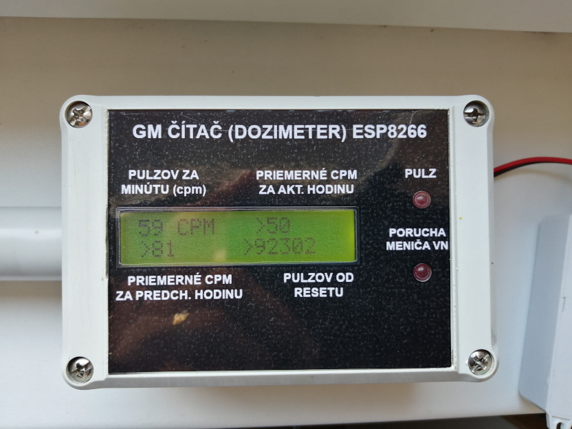
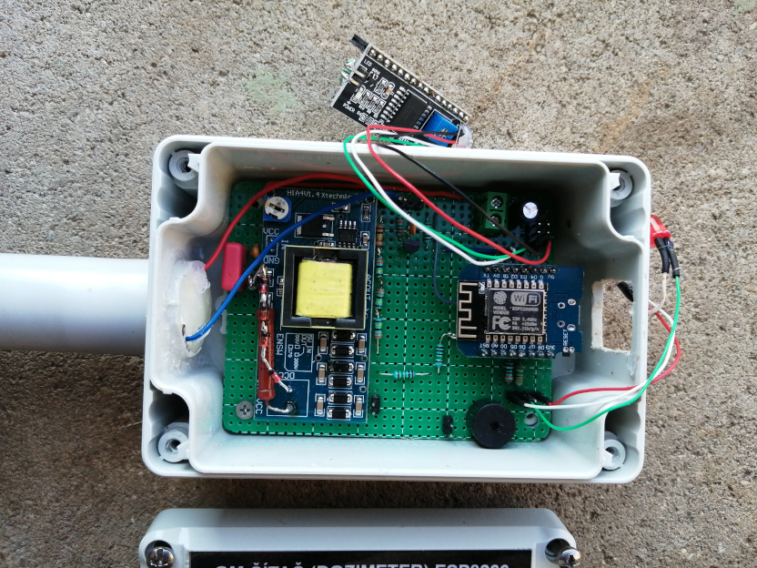
Hello, last week i rebuild my GM counter with Arduino NANO and W5100 ethernet module.
Now I used ESP8266 and circuit is a bit simplified.
Used tube Si22g
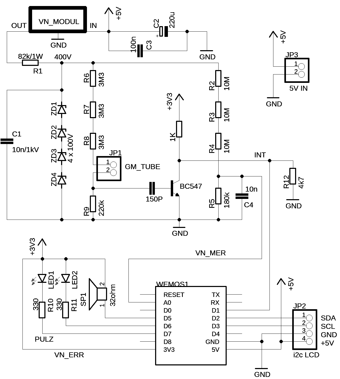
Schematic: schema.png (1302×1450) (pablox.net)
Link to my webpage with article GM čítač s ESP8266 a Si22g (pablox.net)
Hour logs: radmon.pablox.net
Radmon logs: Radiation monitor (radmon.org)

Now I used ESP8266 and circuit is a bit simplified.
Used tube Si22g
Schematic: schema.png (1302×1450) (pablox.net)
Link to my webpage with article GM čítač s ESP8266 a Si22g (pablox.net)
Hour logs: radmon.pablox.net
Radmon logs: Radiation monitor (radmon.org)
Last edit: 2 years 10 months ago by pablox.
Please Log in or Create an account to join the conversation.
2 years 10 months ago - 2 years 10 months ago #6568
by Simomax
Replied by Simomax on topic ESP8266 GM counter schematic + firmware
That looks great pablox! I love the case and front panel - looks very industrial. Nice work, and thanks for sharing the schematic too.
 That PSU looks beefy. I bet that bites if touched wrongly.
I do have a question about the circuit/schematic; why are R2, R3 and R4 10Meg, when you could have used a 30Meg resistor? Same for R6, R7 and R8. They could have been a 10Meg resistor, or whatever is needed for the tube.
ETA: I have just realized this is a new version/upgrade of the version you posted a few months ago. Its looking much nicer, neater and tidier. A massive improvement.
Last edit: 2 years 10 months ago by Simomax.
Please Log in or Create an account to join the conversation.
2 years 10 months ago #6573
by nu3e
Replied by nu3e on topic ESP8266 GM counter schematic + firmware
Resistors have a maximum voltage rating. By placing 3 equal value resistors in series, the voltage drop across each resistor is approximately 400/3.I do have a question about the circuit/schematic; why are R2, R3 and R4 10Meg, when you could have used a 30Meg resistor? Same for R6, R7 and R8. They could have been a 10Meg resistor, or whatever is needed for the tube.
Please Log in or Create an account to join the conversation.
Moderators: Gamma-Man
Time to create page: 0.132 seconds