New weather station build
1 year 7 months ago #6951
by Simomax
New weather station build was created by Simomax
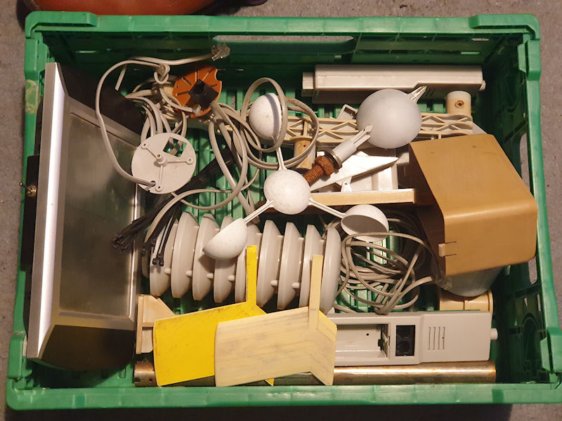
About 4 years ago my weather station failed. It was only a cheap WH1080 from Maplin, but it did it's job for about 8 years. The sensors were getting a bit janky and then the transmitter stopped working. I managed to find a replacement transmitter in China and that did pair with my receiver, but I think the receiver is also broke, or the two aren't quite compatible as I can't save the settings on the receiver and Cumulus is telling me that it is getting some duff data. Now it lies in pieces as shown in the picture. Next stop.... the scrap bin.
Looking for a replacement, ideally a Davis or similar ilk, I realised how damn expensive they are! I don't have a grand (£1000) to throw at a couple of spinney things that make some numbers! Looking at cheap ones that may work with Cumulus... Well, I couldn't really find any. At least not for a good price or a guarantee it would work with Cumulus. So then I looked at Arduino weather station projects and it does appear that most of the heavy lifting with the calculations for wind speed and such are already done. I know how to calculate dew points and wind chill, heat index etc so really it should just be a case of putting everything together on an ESP32 or something. Here is someone else's project from about 6 years ago: https://openweatherstation.com/ows/index.php This uses the same sensors as my own, so the code should work fine with mine. All I have to do is assimilate it.
I decided that I will refurbish my old sensors (anemometer, wind vane and rain gauge) and build a new weather station from scratch and pull some bits of code from wherever and put it all together. So I'll document it all here in case someone finds it useful. At the minute all I have is a crate of bits. I have new bearings for the anemometer and wind vane. I have some BME280s and some Dallas temperature sensors tat I could dig into the soil. I have always fancied that, having a couple of temperature sensors in the ground. One about a meter down and one quite close to the surface. I need to redesign and rebuild the wind vane as I rebuilt it some years back, but over engineered it and made it too heavy. I was trying to make it more accurate, but I think it's a lost cause really due to it's location when outside. So I'll simplify it some and make it lighter this time. It may work, it may not. I am going to modify the rain gauge to increase the surface area of the rain collected. This will increase the resolution of the rain gauge, probably by a factor of about 2. It uses a 'tipping bucket' mechanism to count the water that runs through it and each bucket tip is about 3ml of rain. A larger rain collection surface area will move around twice the amount of rain through the tipping bucket, so effectively making each tip 1.5ml of rain. Having a rain gauge again would be really nice and will complement (or not) some of those occasional radiation rises from time to time.
I was looking about at other weather stations for ideas and inspiration and I found an old weather station display (it may be the processor too) on ebay for £10. So I bid, won and bought it as fast as I could. And it looks awesome! What's not to love about it! I will probably have to heavily modify it, or even just use the case and make my own innards, but this will most certainly be a display for my weather station when I get it running! I love it already!
I'll keep you all posted!
Attachments:
Please Log in or Create an account to join the conversation.
1 year 7 months ago #6955
by Simomax
Replied by Simomax on topic New weather station build
Update #1
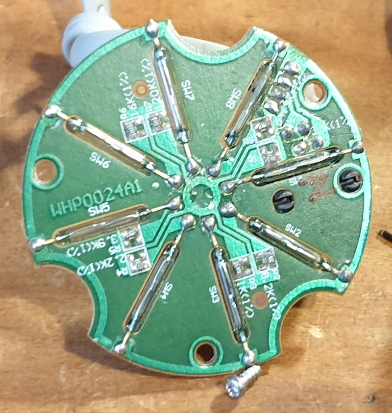
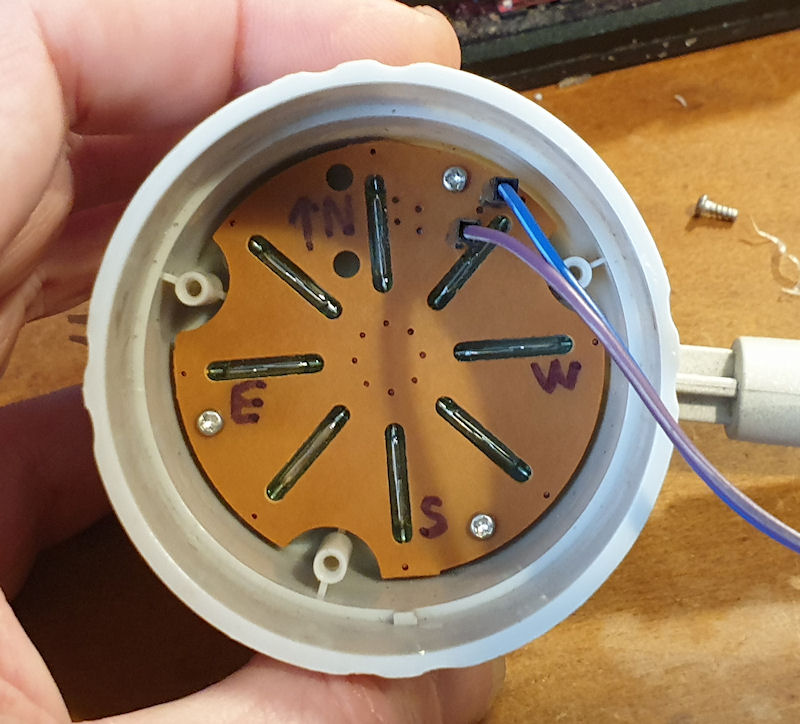
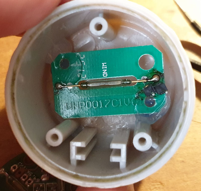
The sensors are good! The electronics are that is. I've checked over the anemometer, wind vane and rain gauge and all are working properly. They are going to need a little work to get them back to shipshape again and I may even pot them in, although the actual board have fared quite well. Only a bit of dull solder on the wind vane PCB. As you can see form the images all the sensors use good, old, conventional reed relays and a magnet on the spinney bit. I may swap these out for hall effect sensors in the future. One thing I would like is a better resolution for the wind vane. As it stands I get N, NE, E, SE, S, SW, W and NW. It would be great to have NNE and ENE etc. around the whole thing. That would also work better (I think) with the wind direction indicator on that ridiculous display I bought.
I am going to swap the cable and RJ connectors for something a bit harder wearing and instead of the anemometer and wind vane being daisy-chained, I will wire each sensor back to a junction box, then an outdoor rated CAT5/6 cable back to the brains. I have already removed the old cable for testing so is just a case of throwing some new cable on it. The wind vane needs rebuilding (physically/mechanically) and I want to modify the rain gauge for a larger surface area, but the anemometer seems quite OK, aside from the PCB mounts failing. All of that should be fairly straight forward.
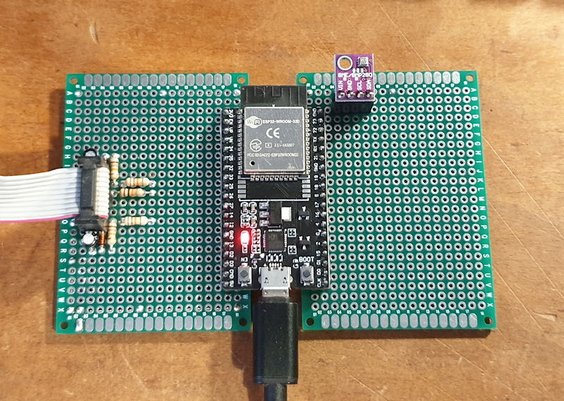
I have thrown an ESP32 onto a protoboard, two actually and got the electronics for the debounce all working. I have assimilated all the code I need from openweatherstation.com and have it working in a very basic fashion. I've soldered header pins onto the sensors for now for testing. I'll remove them when I put new cable in after testing is completed, including verifying the readings and calibrate if needed. That would just be the anemometer and rain gauge though. I have a BME280 running locally at the moment and everything is all going to plan. I need to add some formulas for windchill, heat index, apparent temperature, rainfall rate and Zambretti forecast, all of which is just number crunching code. I am thinking about integrating my Solar Monitor 5 Million in some way with the weather station for displaying UV levels once I have that a little more calibrated, maybe even have a reading for how scorching hot the sun is with the heat collector I made. I have an enclosure on it's way for the ESP/boards and a massive 40x4 LCD (in green! ) that I may use for displaying numbers, for diagnostic purposes mainly. It would be a good project to use that display on. I have even been looking at e-paper displays that I could make a nice display for my desk, or wall.
I also need to work out how I am going record and store the data. I have generally used CSVs for small projects like this, but I may use MySQL this time as it would be much easier to access the data to say compare today with this day last year and things along those lines. MySQL is far easier to dig out records than 100 separate CSVs. My general criteria for the software side is as follows:
Wind vane PCB top
Wind vane PCB bottom
Anemometer - this has one reed switch, but cleverly, it's orientation gives two pulses per revolution
The actual board(s). I made it like this because I didn't have a big protoboard and I wanted plenty of space for mods in the future. The ribbon cable will go to a 8 pin connector to connect to the anamometer, wind vane and rain gauge.
The sensors are good! The electronics are that is. I've checked over the anemometer, wind vane and rain gauge and all are working properly. They are going to need a little work to get them back to shipshape again and I may even pot them in, although the actual board have fared quite well. Only a bit of dull solder on the wind vane PCB. As you can see form the images all the sensors use good, old, conventional reed relays and a magnet on the spinney bit. I may swap these out for hall effect sensors in the future. One thing I would like is a better resolution for the wind vane. As it stands I get N, NE, E, SE, S, SW, W and NW. It would be great to have NNE and ENE etc. around the whole thing. That would also work better (I think) with the wind direction indicator on that ridiculous display I bought.
I am going to swap the cable and RJ connectors for something a bit harder wearing and instead of the anemometer and wind vane being daisy-chained, I will wire each sensor back to a junction box, then an outdoor rated CAT5/6 cable back to the brains. I have already removed the old cable for testing so is just a case of throwing some new cable on it. The wind vane needs rebuilding (physically/mechanically) and I want to modify the rain gauge for a larger surface area, but the anemometer seems quite OK, aside from the PCB mounts failing. All of that should be fairly straight forward.
I have thrown an ESP32 onto a protoboard, two actually and got the electronics for the debounce all working. I have assimilated all the code I need from openweatherstation.com and have it working in a very basic fashion. I've soldered header pins onto the sensors for now for testing. I'll remove them when I put new cable in after testing is completed, including verifying the readings and calibrate if needed. That would just be the anemometer and rain gauge though. I have a BME280 running locally at the moment and everything is all going to plan. I need to add some formulas for windchill, heat index, apparent temperature, rainfall rate and Zambretti forecast, all of which is just number crunching code. I am thinking about integrating my Solar Monitor 5 Million in some way with the weather station for displaying UV levels once I have that a little more calibrated, maybe even have a reading for how scorching hot the sun is with the heat collector I made. I have an enclosure on it's way for the ESP/boards and a massive 40x4 LCD (in green! ) that I may use for displaying numbers, for diagnostic purposes mainly. It would be a good project to use that display on. I have even been looking at e-paper displays that I could make a nice display for my desk, or wall.
I also need to work out how I am going record and store the data. I have generally used CSVs for small projects like this, but I may use MySQL this time as it would be much easier to access the data to say compare today with this day last year and things along those lines. MySQL is far easier to dig out records than 100 separate CSVs. My general criteria for the software side is as follows:
- Record and update displays every 60 seconds (1440 records per day)
- Update wind speed/direction/gusts etc on displays as fast as possible
- Calculate all the fun stuff (heat index, dew point etc etc)
- Display certain readings with rising or falling icons/notes. Basic trending.
- Be able to display any historic readings easily
- All the graphs
- Compare two periods from any two times. This could be today against this day last year, or last month against the month before. After gathering data for a while this would give credence to 'yeah, the weather is much worse this year than last.'
- Show records (highs, lows etc) for all/most sensors. records could be all time, daily, monthly, annually. MySQL would help with this a lot.
- Display on phone one way or another
- Display on web - This has to look like my old weather station page that was fed by Cumulus. It also has to work with the 'Steel Series' gauges I have on the old site - see here: http://www.schmoozie.co.uk/weather/
- Display on desk or wall
- Display to that ridiculous display I bought
- Have alerts. It would be wonderful to be alerted when the wind speed or gusts get to a certain level. Also rainfall. Too much too soon and give an alert.
- Anything I have forgotten
Wind vane PCB top
Wind vane PCB bottom
Anemometer - this has one reed switch, but cleverly, it's orientation gives two pulses per revolution
The actual board(s). I made it like this because I didn't have a big protoboard and I wanted plenty of space for mods in the future. The ribbon cable will go to a 8 pin connector to connect to the anamometer, wind vane and rain gauge.
Attachments:
Please Log in or Create an account to join the conversation.
1 year 7 months ago #6956
by Simomax
Replied by Simomax on topic New weather station build
Update #2
I have just added 'wind chill' to the mix and seems to be calculating correctly. I had to put in some static numbers for testing as wind chill is only valid when the wind is moving more than 3mph (4.83kph/1.34ms) and the temperature is below 10°C.
This is the formula: T_wc = 13.12 + 0.6215 * T_a * (0.3965 * T_a - 11.37) * v^0.16
Where:
T_wc is the wind chill in Celsius temperature scale,
T_a is the air temperature in degrees Celsius,
v is the wind speed in kilometers per hour.
This is the output with static wind (10MPH) and temp (9°C):
Temperature: 9.00 | Humidity: 45.36 | Dew Point: 0.00 | Pressure: 1001.54
Wind Speed (ms): 4.47 | Wind Speed (mph): 10.00 | Wind Speed (kph): 16.09 | Wind Chill: 6.54
Wind Angle: 315 | Wind Gust (ms): 0.00 | Gust Angle: 0.00
Rain mm: 0.00 | Uptime: 30013
Please Log in or Create an account to join the conversation.
1 year 7 months ago - 1 year 7 months ago #6961
by Simomax
Replied by Simomax on topic New weather station build
Update #3
My head hurts.... I have been banging away at getting all the fuzzy formulas in for calculating all the 'feels like' readings. I'm almost there but need to revisit a couple as I'm not happy with the results. So far I have programmed in the following:
These are the readings I am now getting:
I received the Marex weather station display. Its awesome. I love it forever! It looks and feels hand built. I had a stint on an assembly line back in the 90's making expensive fire alarm panels for some MOD contract. This looks, feels, smells and tastes just like the panels I was building back then. Massively over engineered and ridiculously expensive parts used. My Dad used to work for British Aerospace and would bring home all sorts of control panels and things from scrap for me to play with when I was a kid. thjs reminds me of the kind of stuff he used to get.
I really doubt there is any chance of me using it as is, or with light modification. It seems to have a single wire for data input and then the control board does whatever and sends data along a bus, where it is picked up by each module. Without knowing what kind of data was inputted it would be probably impossible to reverse engineer it to feed it the right data. having a look at the modules and the LED drivers, they seem complex. Much of which would be done in a single IC these days. I'm going to look into it more and see if I can get the LED segments working with the existing chips, but it's doubtful. I think I ma have to strip the PCBs right down to just the parts I want (LEDs) and drive them another way. I suspect a daughter board and a marathon of soldering is imminent!
The engineering in that unit is crazy, and expensive. It has a zillion-way connector for 4 wires.... Really, just 4 wires..... The PSU looks a good'n. Made by Volgen and even has Nichicon caps to boot! If it has Nichicons, everything else will be a good spec. The control board is boring. It has a CMOS UART and some glue logic. I think it also ahs some kind of power switch with a FET that turns the thing on and off when data is received or not. Plugging it in and turning on only shows an 'On' indicator and nothing else. It was also sold as 'does not power on'.
Alright, until the next update I'll leave you with this picture, and if you want to view the hi-res pictures you can download them here: https://www.schmoozie.co.uk/download/marex_weather_station_display.zip
My head hurts.... I have been banging away at getting all the fuzzy formulas in for calculating all the 'feels like' readings. I'm almost there but need to revisit a couple as I'm not happy with the results. So far I have programmed in the following:
- All the usual (wind/temp/humidity/pressure etc.)
- Absolute humidity (needs work)
- Dew Point
- Humidex
- Apparent Temperature
- Heat Index
- Water Vapour Pressure (needs work)
- Wind Chill
These are the readings I am now getting:
Temperature (°C): 28.20 | Temperature (°F): 82.76 | Relative Humidity (%): 44.04 | Absolute Humidity (%)*******: 27.31 | Dew Point (°C): 14.83 | Humidex: 32.07 | Apparent Temp (°C): 29.86 | Heat Index (°C): 28.15 | Water Vapour Pressure (hPa)*******: 22.38 | Pressure (hPa): 1004.78
Wind Speed (ms): 0.00 | Wind Speed (mph): 0.00 | Wind Speed (kph): 0.00 | Wind Chill (°C): 28.20
Wind Angle (°): 270 | Wind Gust (ms): 0.00 | Gust Angle (°): 0.00
Rain mm: 0.00 | Uptime: 2320013
I received the Marex weather station display. Its awesome. I love it forever! It looks and feels hand built. I had a stint on an assembly line back in the 90's making expensive fire alarm panels for some MOD contract. This looks, feels, smells and tastes just like the panels I was building back then. Massively over engineered and ridiculously expensive parts used. My Dad used to work for British Aerospace and would bring home all sorts of control panels and things from scrap for me to play with when I was a kid. thjs reminds me of the kind of stuff he used to get.
I really doubt there is any chance of me using it as is, or with light modification. It seems to have a single wire for data input and then the control board does whatever and sends data along a bus, where it is picked up by each module. Without knowing what kind of data was inputted it would be probably impossible to reverse engineer it to feed it the right data. having a look at the modules and the LED drivers, they seem complex. Much of which would be done in a single IC these days. I'm going to look into it more and see if I can get the LED segments working with the existing chips, but it's doubtful. I think I ma have to strip the PCBs right down to just the parts I want (LEDs) and drive them another way. I suspect a daughter board and a marathon of soldering is imminent!
The engineering in that unit is crazy, and expensive. It has a zillion-way connector for 4 wires.... Really, just 4 wires..... The PSU looks a good'n. Made by Volgen and even has Nichicon caps to boot! If it has Nichicons, everything else will be a good spec. The control board is boring. It has a CMOS UART and some glue logic. I think it also ahs some kind of power switch with a FET that turns the thing on and off when data is received or not. Plugging it in and turning on only shows an 'On' indicator and nothing else. It was also sold as 'does not power on'.
Alright, until the next update I'll leave you with this picture, and if you want to view the hi-res pictures you can download them here: https://www.schmoozie.co.uk/download/marex_weather_station_display.zip
Attachments:
Last edit: 1 year 7 months ago by Simomax.
Please Log in or Create an account to join the conversation.
1 year 7 months ago #6962
by Simomax
Replied by Simomax on topic New weather station build
I forgot to mention, I have been toying around with the idea of using a real time clock and throwing an sd card into the mix. I could record all readings locally as well as on my web server. If the web server ever went down the ESP32 could make a note of the time and then when the server came back online it could upload (post, one by one) the records to the server. That way it shouldn't miss any readings unless the ESP32 went down for any reason. I could also use the sd card as a buffer of sorts for calculating things like rising or falling temps, or rising/falling pressure. It may also be necessary for the forecasting.
The following user(s) said Thank You: Juzzie
Please Log in or Create an account to join the conversation.
1 year 7 months ago #6964
by Simomax
Replied by Simomax on topic New weather station build
Update #4
My head still hurts.... But I am making progress.
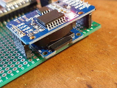
I have added an RTC ( DS3231 ), a micro SD card and a GPS receiver ( NEO-6M GPS Module ). The RTC is just for keeping time and date. The RTC will be set every hour, or 24, or whenever, to the GPS time. I need to have a think about UTC/BST for recording and displaying. Do I record everything in UTC and have adjustment on display, or do I set the RTC twice a year into UTC/BST and record using UTC/BST. The latter would be the most beneficial for displaying and graph creation, but with a caveat that 1 hour of readings will get screwed up when the clock shifts back one hour. Aside from that it would work great and make displaying readings much easier. Only recording in UTC gives a good standard but means that every display has to have the ability to switch from UTC to BST and vice versa, adding an hour, or taking away. The RTC also as an EPROM with each address capable of 1,000,000 writes. That may come in handy if I want to store variables across power cycles. The ESP32 has a flash memory, but is rated for between 10,000 an 100,000 writes so if I were to use flash or EPROM, the RTC EPROM would be the better to use in terms of number of writes.
The SD card is for recording all readings forever, until the card is full and then it can overwrite old days. It will also store data from the past # hours for use in showing trends. It could also log things like sudden changes so they can be looked at later. Of course the php/mysql could also do this. As the time is recorded on the weather station itself it will be easy to upload and readings if the web server went down for any reason. The weather station is becoming more self contained. Where my old weather station would just send readings to Cumulus (software) and Cumulus would do all the number crunching, the ESP32 seems to have enough oomph to do all the number crunching too. Having it this way simplifies things and makes for a better reliability as it is not reliant on a PC running.
I added the GPS for a few reasons; It has very accurate time and can be used to set the RTC. It is faster than NTP (as in the data is already there in the ESP32, no need to fetch it), requires less programming and resources, is not reliant on the internet and rules out any misconfiguration. I'm also thinking about the future. This weather station could quite easily be mobile, or in a place where there is no internet. The weather station will also record the Lat and Lon and elevation. This could be used if the station was somehow mobile. The elevation data can be used in the fuzzy feels like formulas. The station will also record the number of satellites and HDOP (horizontal dilution of precision (quality of the GPS data/precision.)) The TinyGPS++ library also has a couple of interesting examples for tracking satellites and recording their elevations, but I am unsure if this data would be of any use.
I have also been bashing away at the code and pulling it all together. I still have to dig out my large LCD screen and program that and fix two fuzzy feels like formulas. And I have to fix the weather vane, but I am waiting on parts for that. I don't know what material to use for the tail. I would like something like a waterproof foam board, that can be sanded and profiled. Something that is strong enough to cope with the wind and rain, but also light enough. My 2nd version of the tail was made from balsa and even with a good few coats of paint it only lasted a couple of years. The 3rd version was 3D printed and whilst looking great, it was too heavy. And then there is the Marex display too. I have been looking at that a little and seems I should be able to drive the 7 segment displays and other LEDs too without too much work. The 7 segment displays are all common anode and it looks like the MAX7219 IC will drive them with some extra footering. This IC could also be used for the wind direction indicator. I could use an Arduino Mega and drive each wind direction LED individually! I may have to do something like that depending how the circuit arrangement with the LEDs is.
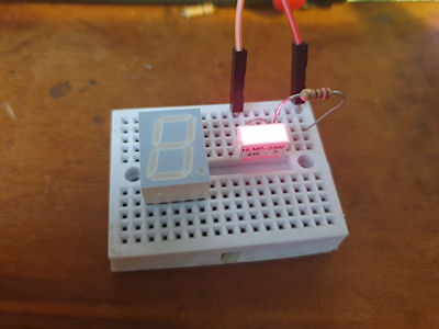
This is the temperature display board and all the cathodes for the 7 segment LEDs are all wired in parallel, leaving the common anodes separate. So each segment is wired together but the anode for each is separate. Two of the decimal points are wired to jumper header pins on the back and some decimal points are not connected to anything. I think a MAX7219 IC, an Arduino Pro Mini and a handful of passives should be enough to get each display module working. I would probably have to do the wind direction indicator and the display as two separate MCUs, so a total of 6 Arduino Pro Minis and 6 MAX7219 ICs, a ESP32 or ESP8266 to get the data over WiFi and whatever passives it needs. I can drive 4 7 segment displays directly from an Arduino with 4 transistors and some passives, but not 5 sadly. Also the MAX7219 has current limiting built in, so I can adjust the brightness and requires little other than the IC itself. I think I will completely strip the boards down to everything except the LEDs and button switches and that should give me enough of a clean slate to work with. Keeping the old PCBs and modifying them also keep all the positions of everything good.
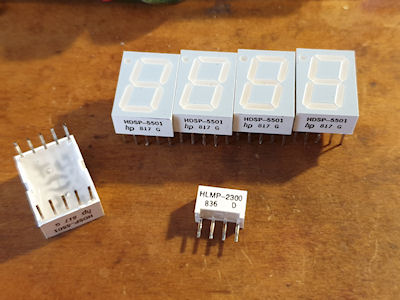
Some LED goodness. The 7 segments are all made by HP and the small rectangle ones are made by Broadcom. They are all still available today. Seems all to good parts got put into this unit. This Marex display would have been a small fortune back in it's day. I have a date too on this unit. It is a 1994 vintage, but the youngest IC in there is a 1993 vintage and the oldest looking to be 1982.
Attachments:
Please Log in or Create an account to join the conversation.
Moderators: Gamma-Man
Time to create page: 0.246 seconds

