
- Forum
- Geiger counter discussions
- Homebrew counters, electronic design and building
- Voltage divider with calibration - for measuring Geiger counter high voltage
Voltage divider with calibration - for measuring Geiger counter high voltage
2 years 1 month ago - 2 years 1 month ago #6984
by Simomax
Some time ago I threw together (what I thought was) a 1000:1 voltage divider for measuring the HV on Geiger counters. This consisted of a Dale 1% 1G ohm resistor (R1) mounted all nice in a box with big chunky gold banana connectors and another quality 1% 1M ohm resistor (R2) connected to a banana socket and then a bunch of croc leads flying about. It worked, but wasn't right. I hadn't accounted for the multimeter's own internal resistance (known as a burden on a circuit). I'm pretty sure my multimeter is a 20M ohm resistance, or thereabouts, so that made R2 actually 950K ohm when the meter was in circuit. So a 1000:0.95 divider. The voltage shown on the multimeter was not that of the HV on the counter. I did some basic testing with and without the divider to confirm this.
As it is essentially a parallel resistor network, a solution was to add some resistance to R2. Increasing that will offset the meter's resistance. If the meter is 20M, then adding 50K to R2 should compensate for this. I decided to build a better divider on proto board that easily plugs in and unplugs from my meter.
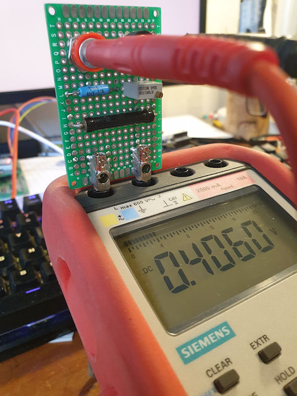
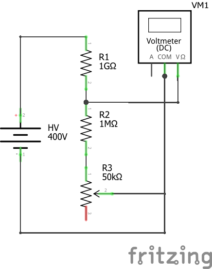
I added a 100K trim pot and set it so when the 1M and pot were measured in series it read 1.05M. I calibrated it using 338VDC from inside a switch mode PSU and it worked really well. I first measured the voltage without the divider and made a note, then put the divider in circuit and whilst reading the voltage I turned the pot until the voltage was the same as without the divider, divided by 1000. It seems to be working very well. I have included the circuit below. *** I have just noticed that the R3 (trim pot) value in the schematic is 50K. It should read 100K. ***
As it is essentially a parallel resistor network, a solution was to add some resistance to R2. Increasing that will offset the meter's resistance. If the meter is 20M, then adding 50K to R2 should compensate for this. I decided to build a better divider on proto board that easily plugs in and unplugs from my meter.
I added a 100K trim pot and set it so when the 1M and pot were measured in series it read 1.05M. I calibrated it using 338VDC from inside a switch mode PSU and it worked really well. I first measured the voltage without the divider and made a note, then put the divider in circuit and whilst reading the voltage I turned the pot until the voltage was the same as without the divider, divided by 1000. It seems to be working very well. I have included the circuit below. *** I have just noticed that the R3 (trim pot) value in the schematic is 50K. It should read 100K. ***
Attachments:
Last edit: 2 years 1 month ago by Simomax.
Please Log in or Create an account to join the conversation.

2 years 1 month ago #6985
by nu3e
Replied by nu3e on topic Voltage divider with calibration - for measuring Geiger counter high voltage
This is a nice test and measurement accessory.
There's no danger as-is because the 1G resistor will limit the current, but it would be better if you connect R3 pins 2 and 3. Potentiometer wipers can become intermittent, especially as they age. Then if the wiper loses contact with the resistive element, the voltage divider won't be left floating. This is common engineering practice, e.g., in audio volume control circuits,
There's no danger as-is because the 1G resistor will limit the current, but it would be better if you connect R3 pins 2 and 3. Potentiometer wipers can become intermittent, especially as they age. Then if the wiper loses contact with the resistive element, the voltage divider won't be left floating. This is common engineering practice, e.g., in audio volume control circuits,
The following user(s) said Thank You: Simomax
Please Log in or Create an account to join the conversation.
2 years 1 month ago #6986
by Simomax
Replied by Simomax on topic Voltage divider with calibration - for measuring Geiger counter high voltage
That's a good idea nu3e. I have seen it done both ways in circuits but never really understood one way or another. I've never really thought about it in all honesty. It makes perfect sense. I shall make that change when I next have my iron hot.
Something I forgot to mention was that R3 could be swapped for a higher value. Say something along the lines of 500K. this would allow the divider to work with lower resistance meters. Using a value such as 500K should allow for meters with an internal resistance as low as 3M, and up to infinity.
Something I forgot to mention was that R3 could be swapped for a higher value. Say something along the lines of 500K. this would allow the divider to work with lower resistance meters. Using a value such as 500K should allow for meters with an internal resistance as low as 3M, and up to infinity.
Please Log in or Create an account to join the conversation.
- ChrisLX200
-

- Offline
- Elite Member
-

Less
More
- Posts: 161
- Thank you received: 8
1 year 3 months ago #7273
by ChrisLX200
Replied by ChrisLX200 on topic Voltage divider with calibration - for measuring Geiger counter high voltage
Surprising what you can find in the forum when you take the trouble to look. I just posted on this subject stating I bought a HV probe to measure tube working voltage ")
Pretty sure most of my meters are 10M Ohm impedance, a FLuke 87V, Bryman 896S, UNI-T UT70D, Rigol DM305B, JTech IDM97, Agilent 34401A. Test quite easily by connecting one to another then set one for voltage and the other for resistance. Then swap Ohm/Voltage to get the other meter's readout. Anyway, I like the compact layout and would make one but I don't have suitable resistors to hand.
Pretty sure most of my meters are 10M Ohm impedance, a FLuke 87V, Bryman 896S, UNI-T UT70D, Rigol DM305B, JTech IDM97, Agilent 34401A. Test quite easily by connecting one to another then set one for voltage and the other for resistance. Then swap Ohm/Voltage to get the other meter's readout. Anyway, I like the compact layout and would make one but I don't have suitable resistors to hand.
Please Log in or Create an account to join the conversation.
1 year 3 months ago - 1 year 3 months ago #7275
by Simomax
Replied by Simomax on topic Voltage divider with calibration - for measuring Geiger counter high voltage
That voltage divider I built has become one of my super handy tools. I would be lost without it now. It simply goes inline with my probes and instantly allows me to measure high impedance power supplies, as well as higher voltages than the meter wouldn't normally handle. I have used it up to 1500v, and it didn't blow up!
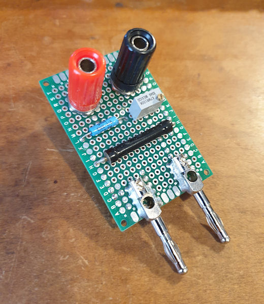
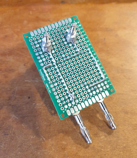
 R1 is a Welwyn Panclimatic 021-6655 (I think) 1M0 1% 200ppm, but I forget what voltage it is rated for. Something else the markings have rubbed off. The other is a Dale RNX-3/8 1G0 1.5kv 1% 100ppm. They are both probably overkill for what I am using them for but the 1% tolerance was key for me. The pot for calibration is just gravy. I'd build another right away if I lost this one. I have found it invaluable for measuring and setting Geiger counter PSUs. I doubt I would ever use it for more than 1000v, maybe occasionally. My probes are CATIII 1000v, so that's quite handy, and the banana sockets for the probes are also binding posts (I take the plastic part off to plug probes in) so it fits the bill in many ways. A very neat, handy, universal voltage divider. I'd be lost without it!
Oh, the resistors I got form ebay - NOS. The pot came out of something else and the banana plugs and binding posts were new, I think, cheap, but OK. The total cost of everything was roughly £15. Each resistor were about £5 each. I have been toying with the idea of making a modern version using modern components such as Murata resistors as they are quite available and have some good specs for cheap. The only downside is ordering in bulk. I was thinking along the lines of have a 10:1, 100:1 & 1000:1 divider on one board, selectable by dip switch or jumpers, and with a 100k pot for calibration. I've never gotten around to it, as the cost for the components came to a lot due to having to buy in bulk, or high shipping costs. I'll have to revisit that soon.
Oh, the resistors I got form ebay - NOS. The pot came out of something else and the banana plugs and binding posts were new, I think, cheap, but OK. The total cost of everything was roughly £15. Each resistor were about £5 each. I have been toying with the idea of making a modern version using modern components such as Murata resistors as they are quite available and have some good specs for cheap. The only downside is ordering in bulk. I was thinking along the lines of have a 10:1, 100:1 & 1000:1 divider on one board, selectable by dip switch or jumpers, and with a 100k pot for calibration. I've never gotten around to it, as the cost for the components came to a lot due to having to buy in bulk, or high shipping costs. I'll have to revisit that soon.
Last edit: 1 year 3 months ago by Simomax.
Please Log in or Create an account to join the conversation.
- ChrisLX200
-
- Offline
- Elite Member
-
Less
More
- Posts: 161
- Thank you received: 8
1 year 3 months ago #7279
by ChrisLX200
Replied by ChrisLX200 on topic Voltage divider with calibration - for measuring Geiger counter high voltage
I do like the compact neat design and will probably make one anyway. However I would be wary of poking around inside a HV power supply with it as parts are quite exposed. It really needs a protective enclosure but that's not a problem. You're safe the other side of the 1G resistor (in theory) but arcing can still occur. That's one advantage of the dedicated HV probe - you are well protected from any arcing HV.
Please Log in or Create an account to join the conversation.
Moderators: Gamma-Man
- Forum
- Geiger counter discussions
- Homebrew counters, electronic design and building
- Voltage divider with calibration - for measuring Geiger counter high voltage
Time to create page: 0.181 seconds