
- Forum
- Geiger counter discussions
- Vintage Geiger Counters
- Very strange Geiger counter from Russia - BIR-3
Very strange Geiger counter from Russia - BIR-3

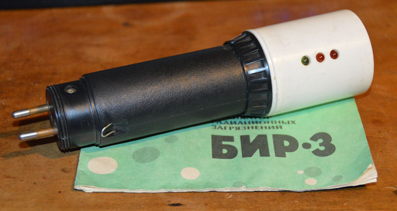
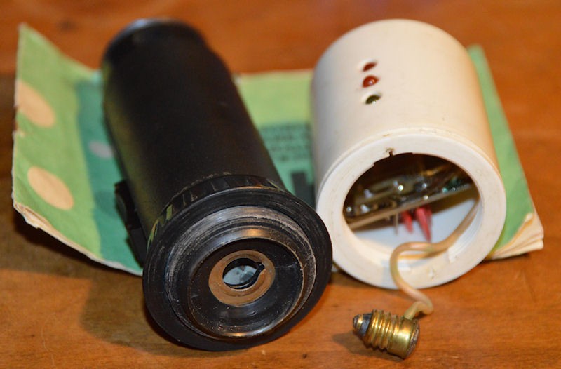
I haven't powered it on yet as I have no idea what battery it should be, if it should be a battery at all. It has US mains plug pins on one end but there is nothing wired to it, nor is there a battery cover. The only way to put a battery in is to disassemble the unit, which is rather cumbersome. It looks to be a flashlight made into a counter, but comes with a printed manual. Almost as though a company has been using flashlight cases and putting a counter inside. It is almost like a PSU has been taken out. Really strange. Everything about it seems homebrew, but it has proper instructions that I need to translate and the cover does state 'Domestic Indicator Radiation Pollution BIR-3' and even has BIR-3 moulded into the end of the white part.
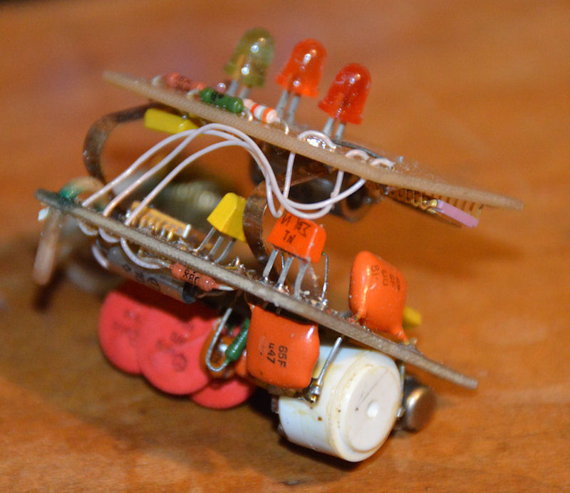
It has three LEDs, red, orange and green and what looks to be a sounder. The sounder, if it is that, is beneath a hole drilled into the end of the white part, I assume to let the sound out! I think the sounder may be an alarm to sound at a certain level, as opposed to a clicker. The construction of the unit as a whole is crazy! It does have what looks like a mini SBM-10 GM tube, which is nice and some very old ceramic ICs. When I get chance I'll try and power this up and see what the ICs are and if the thing works or not. Very strange counter indeed!
Attachments:
Please Log in or Create an account to join the conversation.
Please Log in or Create an account to join the conversation.
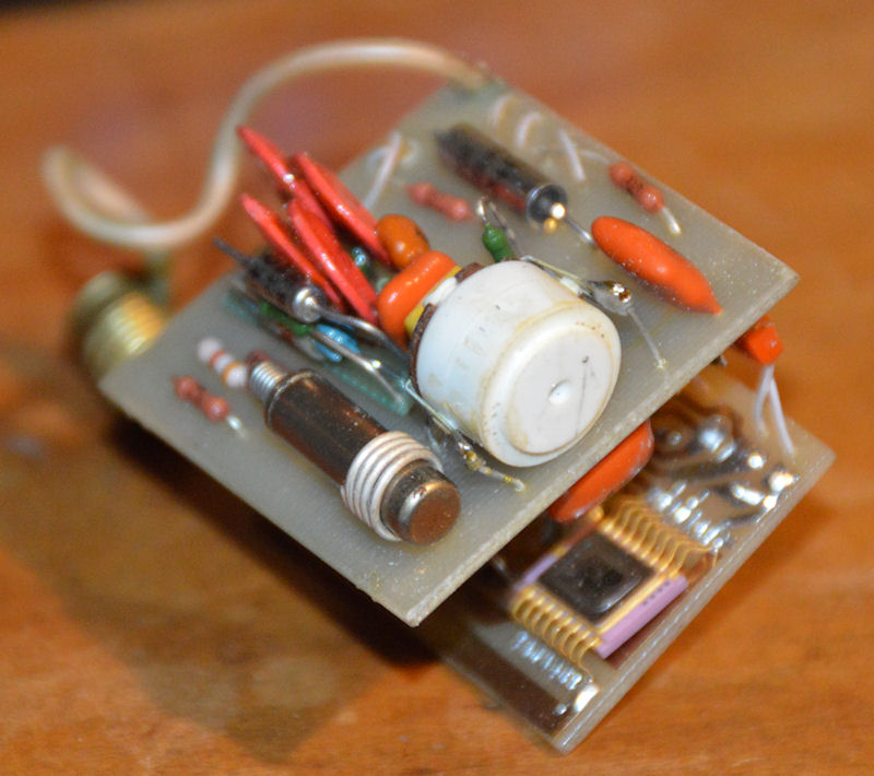
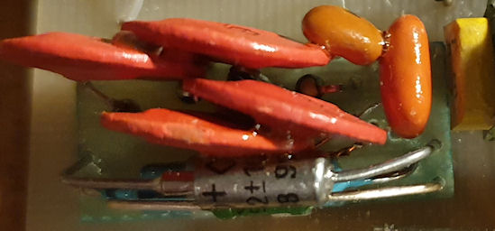
Very interesting. A combination of the custom package IC on the gold lead frame carrier is quite strange. The odd components almost look like cylindrical thermal fuses but I doubt that is what they are. May be capacitors in cylindrical cans. The one part with the wire wound round the can appears to be the detector or a quartz crystal oscillator. Possibly to clock the ASIC in the gold package. The piezo buzzer would indicate counts and the LED's likely show low, medium and high counts. If the can with the wire is the detector it's not very large and I'd wonder how sensitive it could be. The other large can seems to be a capacitor but more pics would be required.
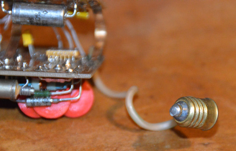
The bulb base to screw into the power adapter may have been an early universal power adapter concept. Perhaps have other components in the lower portion to regulate a power supply for the upper part? At least my best guess. Have you tried to power it up yet? I would probably take a video in case it went up in smoke!
Please Log in or Create an account to join the conversation.
Please Log in or Create an account to join the conversation.

First, here is a video of the unit working. This is running from a 9v battery just pushed against the terminals on the bulb connector. It will run from a 3.6v lipo cell also, but the sounder and LEDs are quite weak, although it does actually detect radiation fine at that voltage.
Interestingly, the orange LED doesn't light orange, but red. The camera picks this up as a different shade of red, but there is little difference to my eye.

I have identified each type of component. The packages whilst similar to the common packages we know of, these seem quite crude in their composition, even for 1990. But this was probably designed and built in the communist USSR era, so would explain that with it being 'domestic' kit.
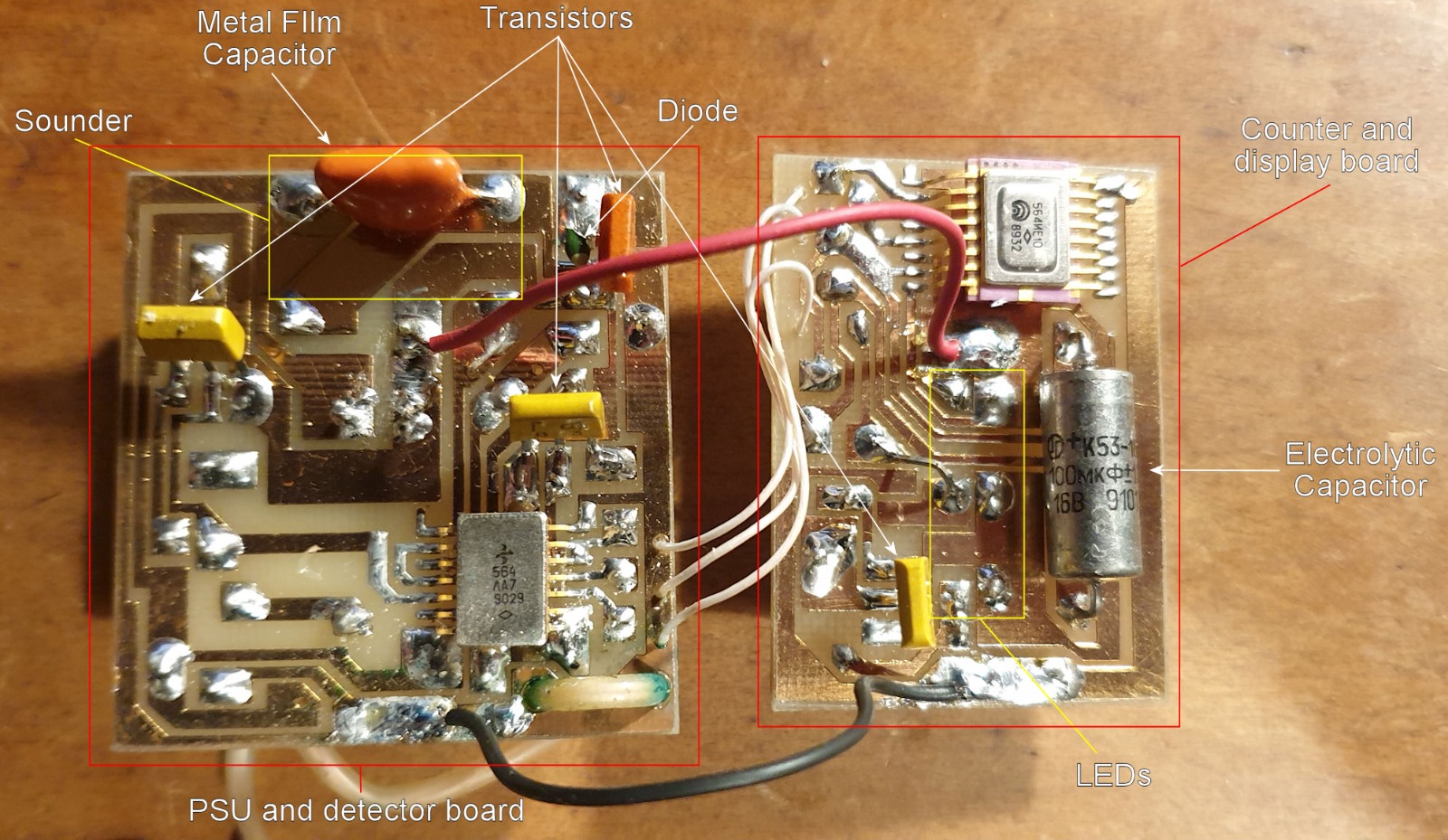
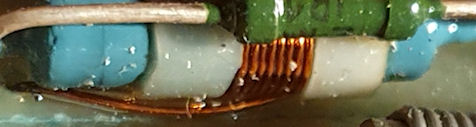
This is the HV PSU with transistor tagged on the end. It is a separate board piggy-backed onto the detector board. As the tube is an SBM-10 (verified as measurements are exact against my known SBM-10) then my assumption is that the HV board generates around 400v. Below that is what I think is the HV transformer. It looks like a coil wound around a wire-wound resistor - very creative! There are diodes that are hard to see next to the large disc capacitors on the HV PSU. This would be a simple pulse generator and voltage quadroupler circuit (two voltage doublers in series.) Hmm, I wonder if that IC on the detector board is used as a ring oscillator to trigger the transistor on the HV PSU? That's plausible.
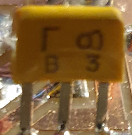
Below is a transistor, and next to that a small signal diode. Probably similar to a 1N4148 but looks to be the same on the HV PSU board, so they may be higher voltage than that. Maybe something like a 1N4004 or 1N4005.
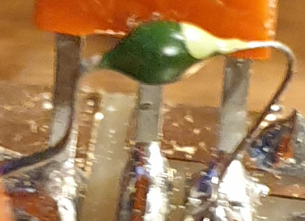
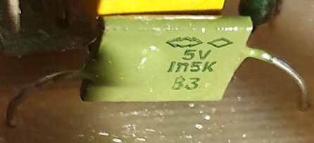
Now, this component got me for a while, until I started tracing the circuit. I'm pretty sure this is a 5V zener diode (I could be wrong.) This is in series with the sounder. From what I can tell the signal goes into a resistor, then the 5V zener, then the sounder. This would make sense if the sounder was rated at 5v with a supply higher than that, such as my 9v battery.
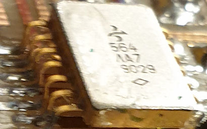
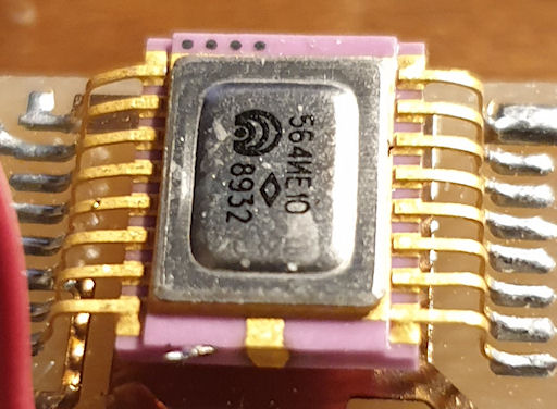
And finally the two ICs. The first is from the HV and detector board. I have little idea what this is or does. It resembles something of a ring oscillator, but there is a lack of capacitors for that. It is much of a puzzle but may be the oscillator for the HV generation. I would have to reverse engineer the actual circuit for that (which I may do in time.) Whereas the 2nd IC is on the display board and I am pretty sure that is something like a logic binary counter. I come to that assumption from the pattern of the LEDs. orange comes on, goes off, red comes on, goes off. both stay off for a bit and both come on, then it starts again. 4-bit binary counter maybe? Its interesting as if I remove the source when an LED is lit they just stay put, as would happen with a binary counter.
I really need to translate the manual as I think that may add some details that I'm missing. Its all quite interesting.

BTW, anyone heard from mw0uzo? Its been nearly a month since he logged in. I hope all is well with him and he is just having a break.
Attachments:
Please Log in or Create an account to join the conversation.
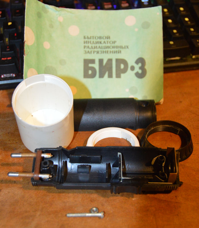
3.1. Structurally, the device is made in the form of a removable indicator head on the basis of a common electric rechargeable pocket flashlight "Lux" and is powered by the same three batteries of type D-0.26, from which the electric lamp of the flashlight was powered.3.2. In the rear part of the device housing, under the removable cap, there is a plug for connecting to an alternating electric current network with a voltage of 127 or 220 V for recharging batteries.
5.2. If the device is switched on in a normal radiation environment, i.e. when there is only a natural background and there is no radiation contamination, then after the readiness only the green indicator will be constantly lit, briefly going out after each measurement period equal to 15-20 seconds.
5.3. After switching on the device, irregular sound signals appear. These signals arise due to the registration of the natural radiation background. The natural radiation background always exists. However, its level is unstable and varies significantly depending on the geographical location, time of day, time of year and a number of other natural factors. Therefore, the frequency of sound signals may vary. In a normal radiation environment (natural radiation-background) the frequency of the sound signals will vary between 2 - 8 per minute. In addition, the presence of sound signals simultaneously indicates the serviceability of the device.
5.4. In an environment with increased radiation, the frequency of sound signals increases. A yellow indicator may flash at the same time. Flashing of the yellow indicator regularly, during each measurement period (15-20 seconds), means that the exposure dose rate is approximately 60 microrentgens per hour or more. This dose, in accordance with the currently accepted norms (see appendix), is the maximum permissible for the population, even when staying around the clock in an environment with such a level of radiation pollution.
5.5. When the environment is polluted to a level that creates an exposure dose rate of about 120 microrentgens per hour or more, a red indicator will be displayed alternately with a yellow indicator during each measurement period (15-20 seconds). In accordance with the existing norms, this is twice the permissible dose for the population, provided that they are in such an environment around the clock.
5.6. With an increase in radiation pollution over 120 microrentgens per hour, the alternating flashing of yellow and red indicators will occur with greater frequency for the same measurement period of 15-20 seconds. Attention! If you have detected a regular flashing of the red indicator, you are advised to leave the contaminated area and report the radiation contamination you have detected to the district sanitary and epidemiological station, the district executive committee or the district police department.
Attachments:
Please Log in or Create an account to join the conversation.
- Forum
- Geiger counter discussions
- Vintage Geiger Counters
- Very strange Geiger counter from Russia - BIR-3